
Solar energy and air source heat pump coupled hot water, heating and refrigerating system and control method thereof

An air source heat pump and refrigeration system technology, applied in solar heating systems, solar collector controllers, solar thermal energy, etc., can solve the problems of low system heat and insufficient heat utilization efficiency, and achieve high heat utilization efficiency and good energy saving The effect that there is much effect, water capacity

Active Publication Date: 2021-10-08
JIANGSU HUAYANG SOLAR ENERGY
View PDF10 Cites 0 Cited by
  • Summary
  • Abstract
  • Description
  • Claims
  • Application Information

AI Technical Summary

Problems solved by technology

[0003] Its shortcoming is: the domestic hot water and heating of the device interact with each other, the heat of the system is small, and its heat utilization efficiency is insufficient

Method used


Image

  • Solar energy and air source heat pump coupled hot water, heating and refrigerating system and control method thereof
  • Solar energy and air source heat pump coupled hot water, heating and refrigerating system and control method thereof

Examples


Embodiment 1

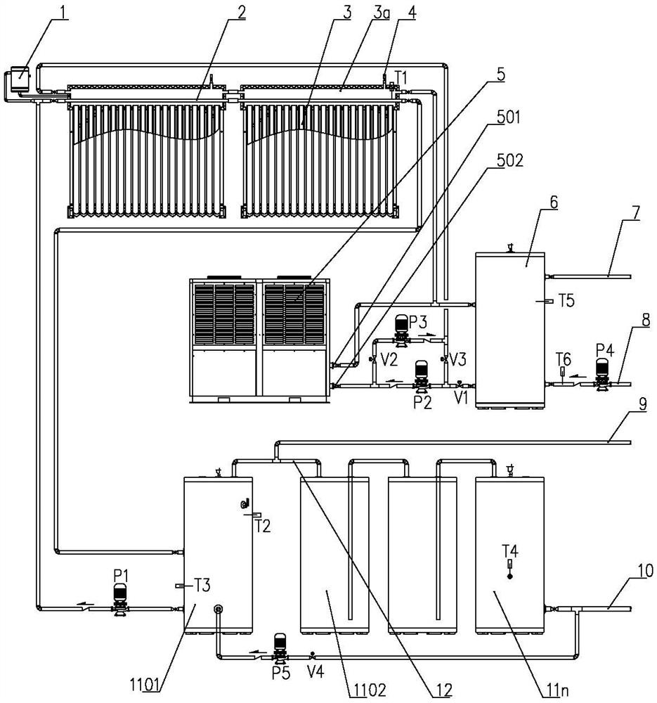
[0027] Such as figure 1As shown, it is a solar energy and air source heat pump coupling hot water, heating and cooling system, including a solar collector 3, an air source heat pump unit 5, a buffer water tank 6, and a storage and exchange water tank. At least two, successively the first heat storage and exchange tank 1101, the second heat storage and exchange tank 1102...the Nth heat storage and exchange tank 11n; the adjacent heat storage and exchange tanks are connected in series through the connecting pipe 12, and one end of the connecting pipe 12 Connected to the top of the storage and exchange water tank, and the other end is inserted into the inner bottom of the adjacent storage and exchange water tank; the connecting pipe 12 on the top of the first storage and exchange water tank 11a is connected to the domestic hot water main pipe 9 through a three-way joint; the water pipe inlet pipe 10 It is divided into two roads through the three-way joint, one road is connected t...

Embodiment 2

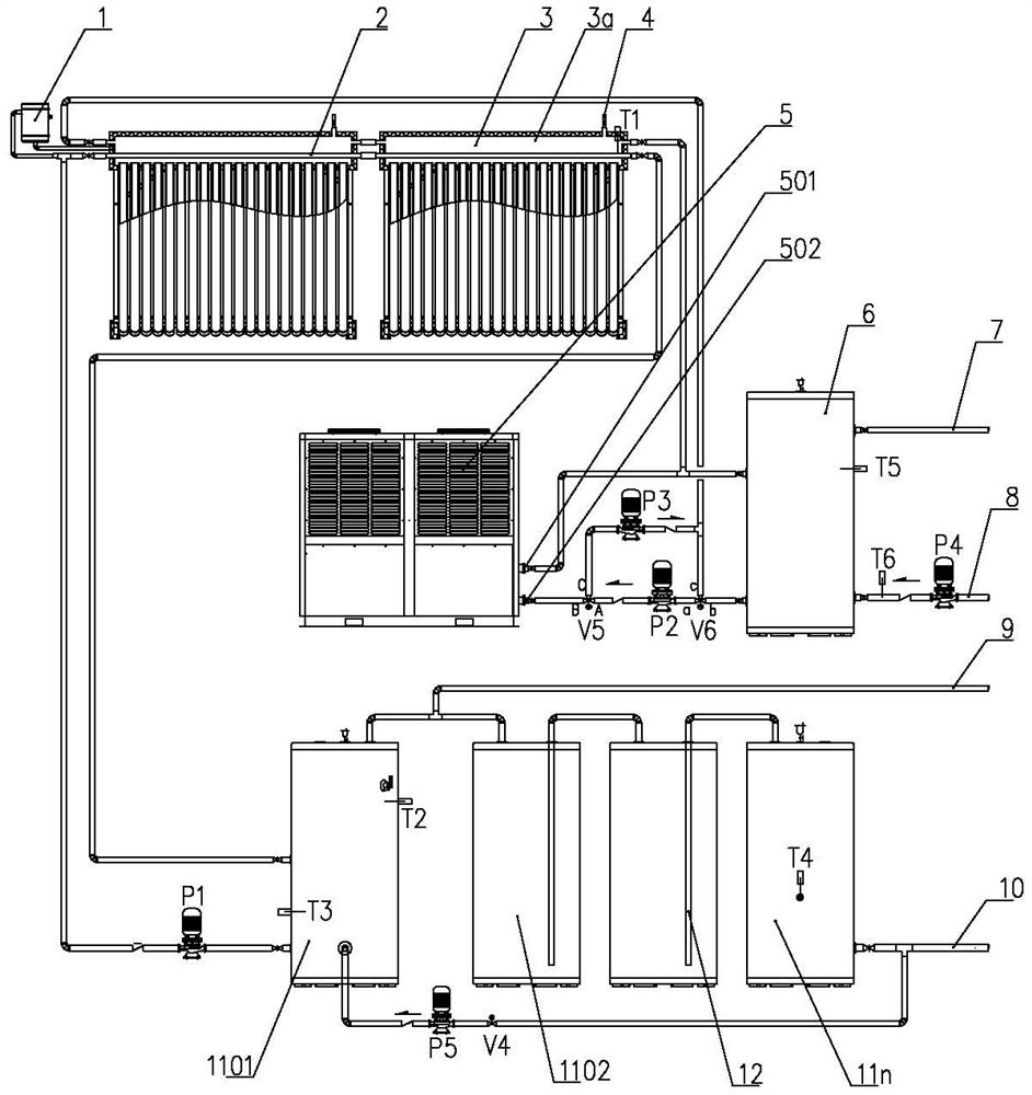
[0047] Such as figure 2 Shown is another structural schematic diagram of the present invention.

[0048] The difference from Embodiment 1 is that the control valve includes a three-way electric control valve V6 arranged between the buffer water tank 6, the inlet of the heat pump circulation pump P2, and the outlet of the third circulation pump P3, and is arranged at the water inlet of the heat pump 502. The three-way electric control valve V5 between the outlet of the heat pump circulation pump P2 and the inlet of the third circulation pump P3.

[0049] The three-way electric control valve six V6 has three paths a, b, and c, and a, b can be connected or a, c can be connected through switching.

[0050] The three-way electronic control valve V5 has three channels A, B, and C, and A, B can be connected or A, C can be connected through conversion.

[0051] Its working modes correspond to working modes 1)-6) of Embodiment 1.


PUM


Abstract

The invention relates to a solar energy and air source heat pump coupled hot water, heating and refrigerating system and a control method thereof in the field of thermotechnical devices. A heat exchange pipe is arranged in a water tank of a solar heat collector, heat transfer is carried out between the heat exchange pipe and heat storage and exchange water tanks, the number of the heat storage and exchange water tanks is at least two, so that preferential use of hot water can be ensured, when the temperature is high, hot water in the first heat storage and exchange water tank is preferentially used through a water storage circulating pump, and when the temperature is low, hot water in other heat storage and exchange water tanks is driven to be preferentially used through the water pressure of tap water; and an air source heat pump unit supplies cold or heat to end equipment through a buffer water tank, hot water can be made in an auxiliary mode through the air source heat pump unit, and in addition, heat energy of the solar heat collector can be used for heating in an auxiliary mode through hot water. The solar heat collector not only can circularly heat domestic hot water, but also can be used for heating at the same time, the two loops do not influence each other, the overall heat utilization efficiency of the system is high, and one machine with multiple purposes can be achieved.

Description

technical field [0001] The invention relates to a thermal device, in particular to a hot water, heating and cooling system coupled with a solar energy and an air source heat pump and a control method thereof. Background technique [0002] In the Chinese patent database, there is a heat pump unit and solar energy linkage heating and domestic hot water device, its publication number: CN102221270A; publication date: 20111019; Buffer water tank and control device; there is a system water supply pipe on the heat preservation water tank, and the domestic water heat exchanger is set in the heat preservation water tank; the main heat pump unit includes a heat pump outdoor unit and an indoor heat exchanger, and the indoor heat exchanger includes an insulation box and a circulation Water pump and a water-refrigerant heat exchanger; the indoor heat exchanger is connected with the thermal insulation water tank and the cold and hot buffer water tank through an electric three-way valve, a...

Claims


Application Information

Patent Timeline
Patent Type & Authority Applications(China)
IPC IPC(8): F25B29/00F25B27/00F25B49/00F24D11/02F24D19/10F24S20/40F24S50/40
CPCF25B29/00F25B27/002F25B49/00F24D11/0221F24D19/1045F24S20/40F24S50/40F24D2200/12F24D2200/14Y02A30/272Y02E10/40Y02B10/20Y02B10/70Y02B30/12
Inventor 邓学鹏
Owner JIANGSU HUAYANG SOLAR ENERGY
Learn More