
A welding device for steel structure installation

A welding equipment and steel structure technology, applied in welding equipment, auxiliary welding equipment, welding/cutting auxiliary equipment, etc., can solve the problems of reducing the use value of welding equipment, cooling, heat loss of welding points, etc. damage effect

Active Publication Date: 2021-11-09
南通泽云机械有限公司
View PDF7 Cites 0 Cited by
  • Summary
  • Abstract
  • Description
  • Claims
  • Application Information

AI Technical Summary

Problems solved by technology

[0004] Based on the existing steel structure, it is generally installed by welding. After welding, the surface temperature of the welding point is high, and the temperature is high, which will easily cause the temperature of the surrounding environment to rise and cause work. The discomfort of personnel, although the temperature of the welding point is high, it cannot be cooled quickly by watering. This cooling method will not only cause damage to the inside of the steel structure, make it lose its original toughness, and reduce the use value. At the same time, the way of watering and cooling will also cause waste of water resources and loss of heat at welding points, reducing the use value of the welding equipment. The invention proposes a welding equipment for steel structure installation

Method used


Image

  • A welding device for steel structure installation
  • A welding device for steel structure installation
  • A welding device for steel structure installation

Examples


Embodiment Construction

[0029] The following will clearly and completely describe the technical solutions in the embodiments of the present invention with reference to the accompanying drawings in the embodiments of the present invention. Obviously, the described embodiments are only some, not all, embodiments of the present invention.

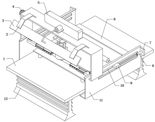
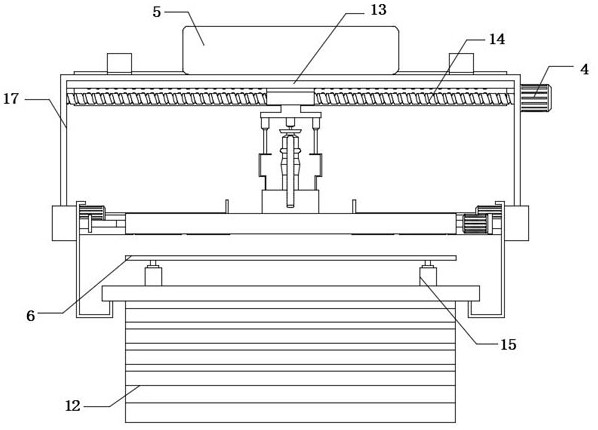
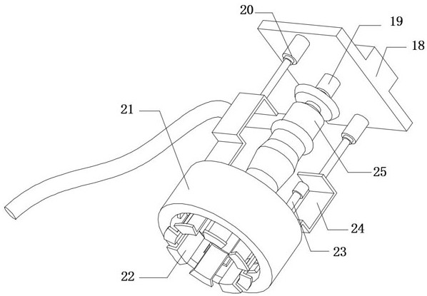
[0030] refer to Figure 1-4, a kind of welding equipment used for steel structure installation, including an operation table 1 and a hanging plate 18, the bottom outer wall of the hanging plate 18 is fixedly connected with a No. 1 hydraulic rod 19, and the bottom outer wall of the No. 1 hydraulic rod 19 is fixedly connected with a welding torch 25, The bottom outer walls of the hanging plate 18 located at both ends of the welding torch 25 are fixedly connected with No. 2 hydraulic rods 20, and the bottom outer walls of the two No. 2 hydraulic rods 20 are fixedly connected with adjustment plates 24. The same cooling water storage ring 21 has a through hole on the top ...


PUM


Abstract

The invention belongs to the technical field of steel structure installation, especially a welding equipment for steel structure installation. The following proposal is proposed, including an operation table and a hanging plate. The outer wall of the bottom of the hanging plate is fixedly connected with a No. 1 hydraulic rod, and a The outer wall of the bottom of the hydraulic rod No. 2 is fixedly connected with a welding torch, and the outer wall of the bottom of the suspension plate located at both ends of the welding torch is fixedly connected with a No. 2 hydraulic rod. The present invention is provided with a rotating motor, a rotating shaft, an extrusion roller, an air cylinder and a sliding rod. Before the installation and welding of the steel structures, the two steel structures are stacked together, and the two steel structures are stacked together through the hierarchical extrusion assembly and the lower support plate below. Carry out clamping and fixing, after fixing, start the rotating motor, and the rotating motor drives the extrusion roller to rotate through the rotating shaft, so as to move and squeeze the steel structure, eliminate the gap between the two before, and prevent the welding effect from being reduced due to the gap after welding. Thereby ensuring the firmness between the steel structures after welding.

Description

technical field [0001] The invention relates to the technical field of steel structure installation, in particular to a welding device for steel structure installation. Background technique [0002] Welding: also known as welding and welding, is a manufacturing process and technology for joining metals or other thermoplastic materials such as plastics by means of heating, high temperature or high pressure; during the installation of steel structures, multiple steel structures need to be welded Pile up, and then perform welding operations on its various points, therefore, need to use welding equipment. [0003] Existing steel structures are generally installed by welding. After welding, the surface temperature of the welding point is high, and the high temperature will easily cause the temperature of the surrounding environment to rise, causing the staff to Discomfort, although the temperature of the welding point is high, it cannot be cooled quickly by watering. This coolin...

Claims


Application Information

Patent Timeline
Patent Type & Authority Patents(China)
IPC IPC(8): B23K37/00B23K37/04B23K37/02B08B5/04
CPCB23K37/00B23K37/003B23K37/04B23K37/0247B08B5/04B23K2103/04
Inventor 王笑天
Owner 南通泽云机械有限公司
Learn More