Construction method of drilling bolt fastener type formwork supporting system

A formwork support and construction method technology, which is applied in the direction of formwork/formwork/work frame, connection parts of formwork/formwork/work frame, and on-site preparation of building components, which can solve the problem of occupying construction space, shortening service life, The installation process is complex and other problems, to achieve the effect of maintaining cleanliness, stable structure, and simplifying the construction process

Inactive Publication Date: 2021-10-15
SOUTHERN CONSTR CO LTD OF CHINA CONSTR EIGHTH ENG DIV
View PDF13 Cites 0 Cited by
  • Summary
  • Abstract
  • Description
  • Claims
  • Application Information

AI Technical Summary

Problems solved by technology

There are usually two types of formwork support in the prior art: one is to tie the formwork on both sides with tension bolts to achieve the purpose of strengthening the side form, but the mounting plate of the tension bolt needs to be drilled on the side form, which reduces the cost to a certain extent. The strength of the side form is shortened, and the service life is shortened. At the same time, there are problems such as complicated installation procedures, time-consuming and labor-intensive installation of the pull bolts.
The second is to set a support structure on the outside of the side form. The support structure is usually a diagonal brace and requires a load-bearing fulcrum, which requires a certain construction space, which is not conducive to the construction, and cannot be used in occasions where the construction space is limited.

Method used


Image

  • Construction method of drilling bolt fastener type formwork supporting system
  • Construction method of drilling bolt fastener type formwork supporting system
  • Construction method of drilling bolt fastener type formwork supporting system

Examples


Embodiment 1

[0058] In a construction project, it is necessary to pour the top beam of the foundation pit, and the size of the top beam of the foundation pit is 3400 (width) * 600 (height) mm.

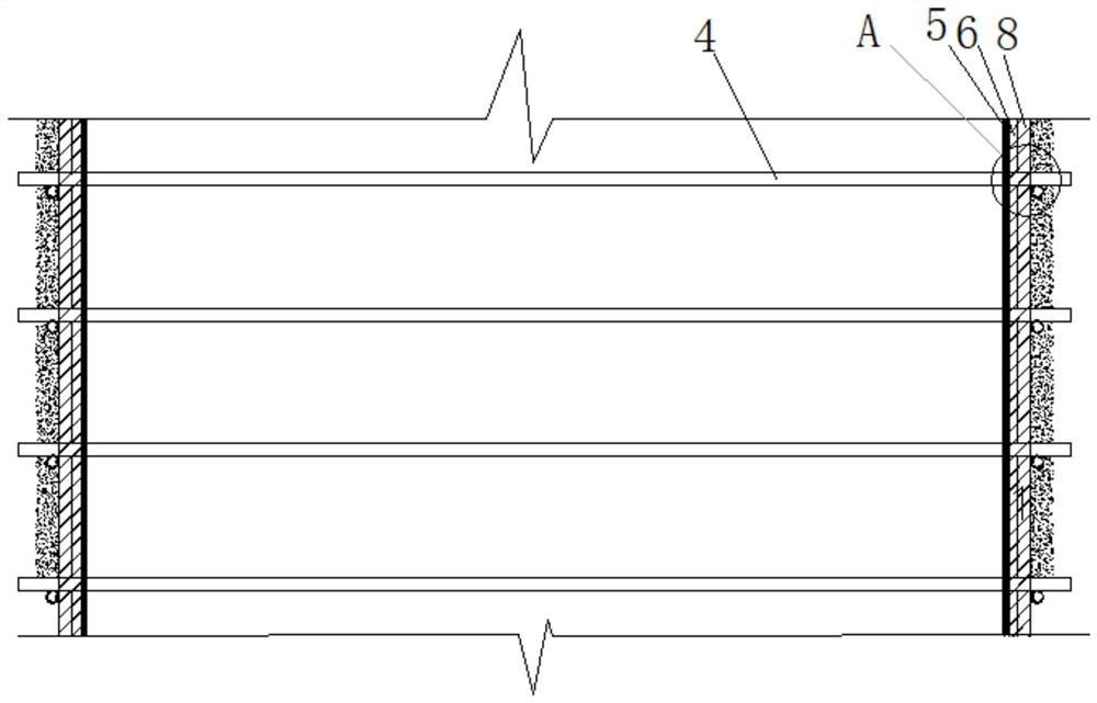
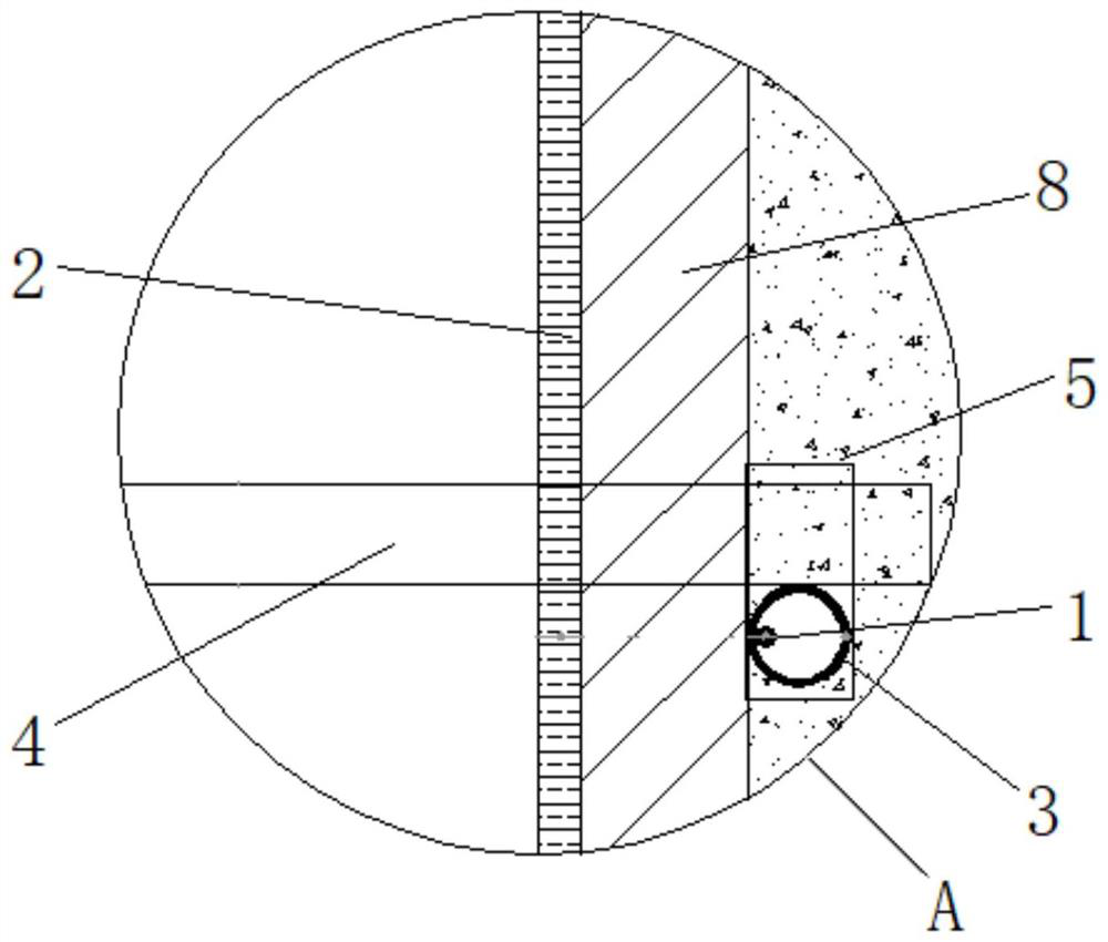
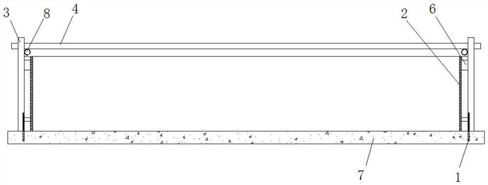
[0059] Step 1: Construction preparation, prepare materials for the formwork support system of drilled bolt fasteners, including inserting ribs 1, side formwork 2, positioning pipe 3, connecting pipe 4, bolt fastener 5, square corrugation 6 and reinforcement pipe 8.

[0060] Step 2: Use an ink fountain to pop out the 3400mm centerline of the foundation pit topping beam on the cushion layer 7, take the 3400mm centerline as the reference, measure 1700mm to one side and use the spring line as the component side line of one side of the foundation pit topping beam, and move to the other side Measure 1700mm from the side and snap the line as the component edge on the other side of the foundation pit top beam.

[0061] In the present embodiment, the side formwork 2 adopts plywood with a thickness of 18mm, ...


PUM


Abstract

The invention discloses a construction method of a drilling bolt fastener type formwork supporting system. The construction method comprises the steps that 1, joint bars (1), side formworks (2), positioning pipes (3), connecting pipes (4) and bolt fasteners (5) are prepared; 2, joint bar lines are symmetrically arranged on cushion layers (7) on the outer sides of the two side formworks; 3, the joint bars are arranged along the joint bar lines, and the multiple joint bars are symmetrically arranged on the two sides of the two side formworks; 4, the lower ends of the positioning pipes are sleeved with the joint bars and attached to the outer walls of the side formworks, and the upper ends of the positioning pipes are higher than the upper ends of the side formworks; 5, the connecting pipes are connected with the positioning pipes through the bolt fasteners, and the two positioning pipes and the connecting pipes are connected to form an inverted-U-shaped supporting system which is arranged on the outer sides of the two side formworks in a sleeving mode; 6, the steps 4-5 are repeated, and a plurality of supporting systems are arranged in the length direction of a building part at intervals; and 7, concrete is poured. The formwork of the building part can be effectively supported and reinforced, and the construction quality of the formwork and the building part is guaranteed.

Description

technical field [0001] The invention relates to a construction method of a building formwork, in particular to a construction method of a drill bolt fastener type formwork support system. Background technique [0002] In the construction of construction projects, building components such as beams and columns need to be installed with formwork before concrete pouring, and the formwork is supported and fixed through the support system to avoid mold expansion and grout leakage during concrete pouring and other construction processes. There are usually two types of formwork support in the prior art: one is to tie the formwork on both sides with the tie bolts to achieve the purpose of strengthening the side formwork, but the mounting plate of the tie bolts needs to be drilled on the side formwork, which reduces to a certain extent The strength of the side form is shortened, and the service life is shortened. At the same time, there are problems such as complicated installation pr...

Claims


Application Information

Patent Timeline
Patent Type & Authority Applications(China)
IPC IPC(8): E04G13/02E04G13/04E04G17/00
CPCE04G13/02E04G13/04E04G17/00
Inventor 杨松王华平柯树喜谢元勋万凯陈鹏
Owner SOUTHERN CONSTR CO LTD OF CHINA CONSTR EIGHTH ENG DIV
Why Eureka
Try Eureka