Energy supply system and control method thereof

A control method and energy supply technology, applied in the field of multi-generation, can solve problems such as molten salt is easy to solidify, block pipelines, limit the continuous, stable and efficient operation of externally heated engines, etc.

Pending Publication Date: 2021-10-19
ZHEJIANG UNIV
View PDF0 Cites 0 Cited by
  • Summary
  • Abstract
  • Description
  • Claims
  • Application Information

AI Technical Summary

Problems solved by technology

[0004] In the traditional solar concentrating external heat engine thermal power generation system and combined heat and power system, most of them directly heat the high-temperature focused spot directly to the external heat engine heater, which is difficult to achieve uniform heating of the wall surface temperature of the heating tube, which limits the Thermal engine runs continuously, stably and efficiently
[0005] The...

Method used


Image

  • Energy supply system and control method thereof
  • Energy supply system and control method thereof
  • Energy supply system and control method thereof

Examples


Embodiment approach

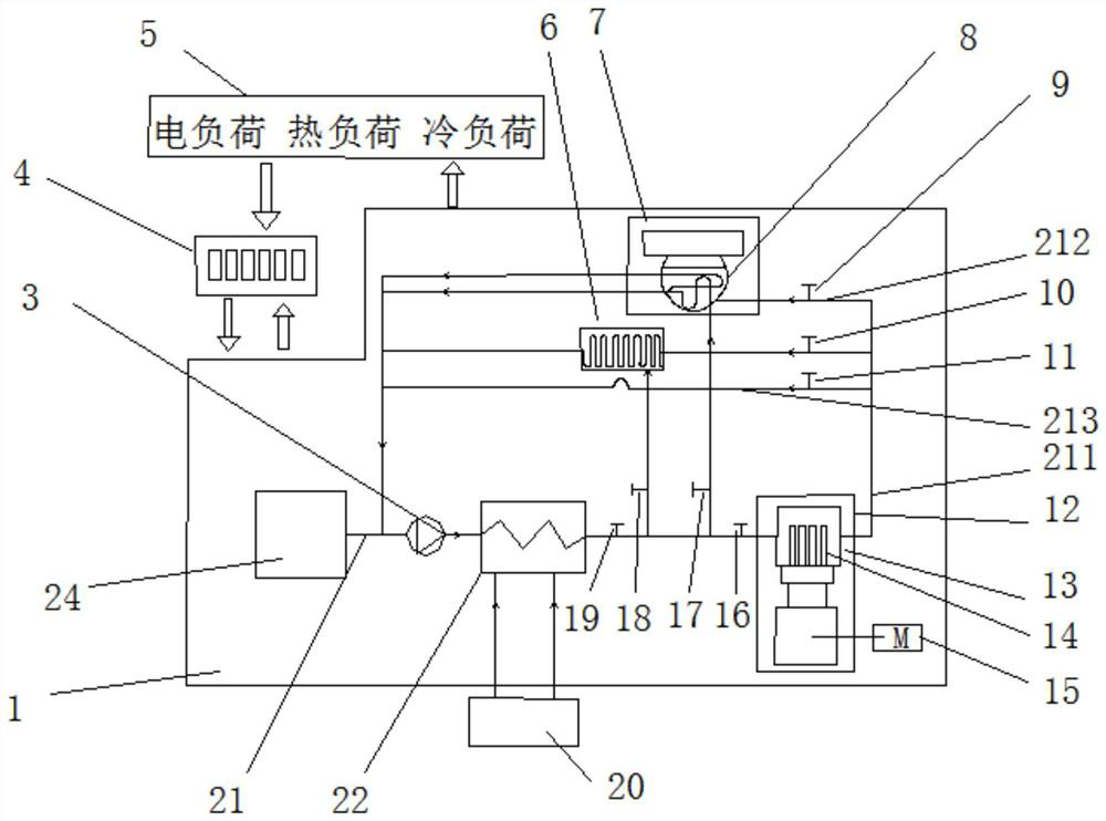
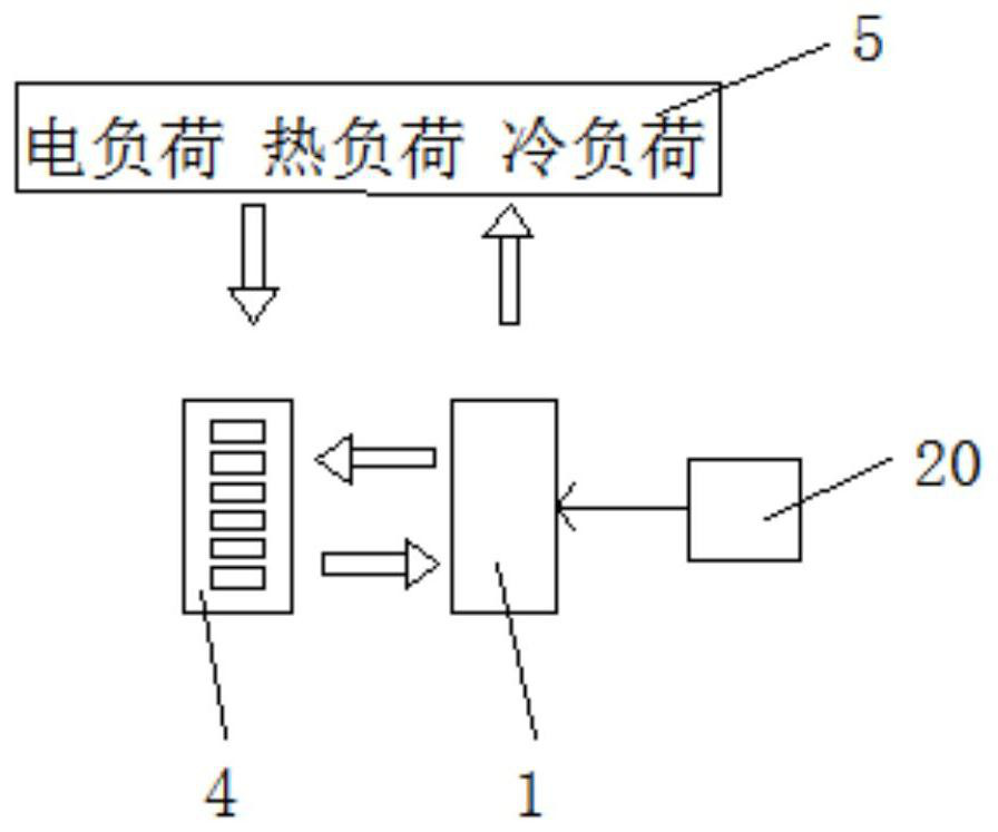
[0048] combine figure 1 with image 3 , an embodiment of the present invention is as follows:

[0049] An energy supply system, comprising an energy co-supply system body unit 1, a control unit 4, an adjustable load 5, and a heat source 20;

[0050] Among them, the main body unit 1 of the energy cogeneration system includes:

[0051] a medium flow path 21 having a heat transfer medium 24 capable of flowing therein;

[0052] The heat source 20 heats the heat transfer medium 24 in the medium flow path 21, and the medium flow path 21 located downstream of the heat source 20 has a first branch 211 and a second branch 212;

[0053] The external heat engine 12 is arranged in the first branch 211, and the heat transfer medium 24 in the first branch 211 heated by the heat source 20 supplies heat to the external heat engine 12;

[0054] The heat / cool load is arranged in the second branch 212, and the heat transfer medium 24 in the second branch 212 heated by the heat source 20 supp...

Embodiment 2

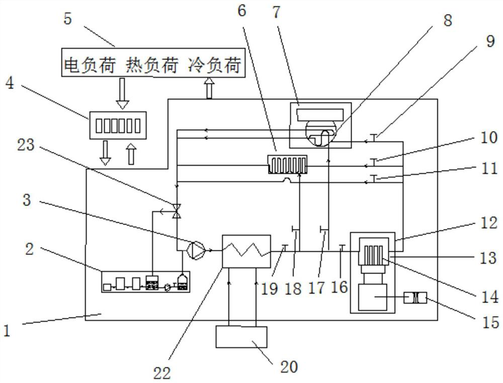
[0091] combine figure 2 , image 3 with Figure 4 , other embodiments of the present invention are as follows:

[0092] The main difference between the second embodiment and the first embodiment is that the heat transfer medium 24 used in this technical solution is water vapor.

[0093] Another difference between Embodiment 2 and Embodiment 1 is that a steam trap 23 and a working medium purification device 2 are added in the main unit 1 of the energy cogeneration system.

[0094] The working medium purification device 2 includes a water source 2a, a desalination device 2b, an oxygen removal device 2c, a water storage tank 2d, a feed water pump 2e, a feed water valve 2f, and a steam generator 2g.

[0095] The supply water from the water source 2a first passes through the desalination device 2b to remove salt impurities in the water; then passes through the deoxygenation device 2c to remove oxygen and other gases in the water to avoid slagging and corrosion in the circulatio...

Embodiment 3

[0104] combine figure 2 , Figure 4 with Figure 5 , other embodiments of the present invention are as follows: on the basis of embodiment two, the main heat source is solar energy, the sunlight heats the medium heater 22 after being concentrated by the secondary dish-type condenser heating unit, and the auxiliary heat source is natural gas.

[0105] In summer or when the temperature is high, the control unit 4 adjusts the medium circulation pump 3, the medium main valve 19, the external heat engine medium inlet valve 16, the cold load medium inlet valve one 9, the cold load medium inlet valve two 17 and the bypass Valve 11 closes heat load medium inlet valve one 10 and heat load medium inlet valve two 18, heat transfer medium 24 heats cold load generator 8 to generate cold energy while heating external heat engine heater 14 to generate electric energy, and realizes Cooling and electricity co-supply and coordination and matching of cooling and electricity loads.


PUM


Abstract

The invention provides an energy supply system and a control method thereof. The energy supply system comprises a medium flow path, a heat source, an external heating type engine and a hot/cold load, wherein the medium flow path is provided with a heat transfer medium capable of flowing in the medium flow path; the heat source is used for heating the heat transfer medium in the medium flow path, and the medium flow path located at the downstream of the heat source is provided with a first branch and a second branch; the external heating type engine is arranged on the first branch, and the heat transfer medium, heated by the heat source, in the first branch supplies heat to the external heating type engine; and the hot/cold load is arranged on the second branch, and the heat transfer medium, heated by the heat source, in the second branch supplies heat to the hot/cold load. The heat transfer medium heated by the heat source flows in the medium flow path, the heat transfer medium supplies heat to the external heating type engine of the first branch and the hot/cold load of the second branch, the external heating type engine absorbs heat to achieve heat-work conversion, the external heating type engine operates stably, the hot/cold load absorbs heat to generate a heat load or a cold load, the problem of energy waste is relieved, and the multi-combined supply requirement is met.

Description

technical field [0001] The invention relates to the technical field of multiple power supply, in particular to an energy supply system and a control method thereof. Background technique [0002] The external heating engine adopts external heating, which has the outstanding advantage of good energy adaptability. Taking the Stirling engine as an example, it is an externally heated (or combusted) piston engine that utilizes the periodic expansion and compression of the working fluid gas sealed in the circuit to realize the conversion of heat energy into mechanical work. [0003] The externally heated engine is connected with the generator, and the engine runs to drive the generator to generate electricity externally. [0004] In the traditional solar concentrating external heat engine thermal power generation system and combined heat and power system, most of them directly heat the high-temperature focused spot directly to the external heat engine heater, which is difficult to...

Claims


Application Information

Patent Timeline
IPC IPC(8): F02G1/043F02G1/045F02G1/053F02G1/055
CPCF02G1/043F02G1/045F02G1/053F02G1/055
Inventor 肖刚邱浩倪明江岑可法
Owner ZHEJIANG UNIV
Why Eureka
Try Eureka