Adjustable sealing device

A sealing device and adjustable technology, applied in the sealing of engines, parts of pumping devices for elastic fluids, non-variable pumps, etc., can solve poor sealing performance, increased energy consumption, and reduced performance of centrifugal fans etc. to achieve the effect of reducing energy consumption, reducing leakage loss and improving fan efficiency

Pending Publication Date: 2021-10-19
CHONGQING GENERAL IND (GRP) LTD
View PDF10 Cites 0 Cited by
  • Summary
  • Abstract
  • Description
  • Claims
  • Application Information

AI Technical Summary

Problems solved by technology

[0004] The purpose of the present invention is to provide an adjustable sealing device to solve the poor sealing performance of the existing sealing device, and some gas enters the atmosphere from the casing and the main shaft, resulting in a decrease in the performance of the centrifugal fan and an increase in energy consumption The problem

Method used


Image

  • Adjustable sealing device
  • Adjustable sealing device
  • Adjustable sealing device

Examples


Embodiment Construction

[0015] The following is further described in detail through specific implementation methods:

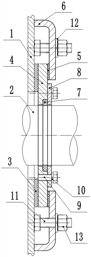
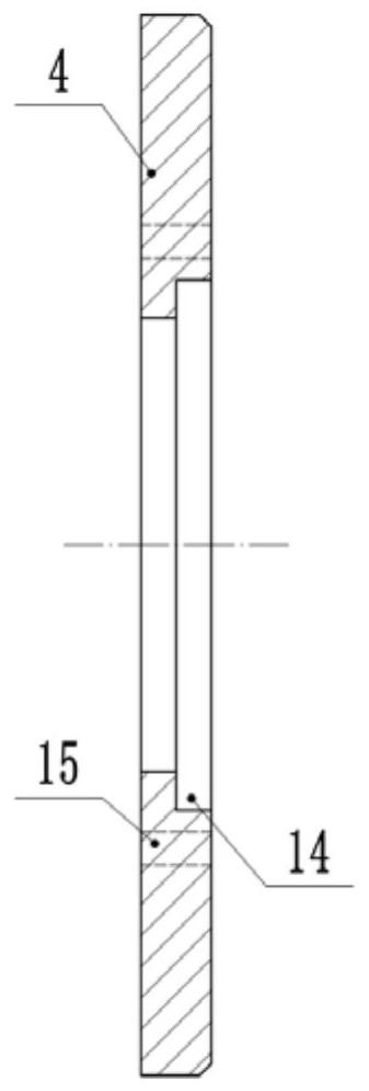
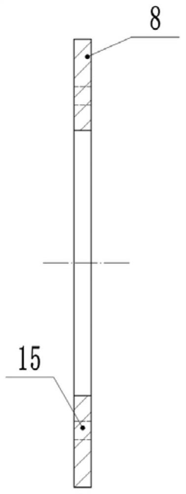
[0016] The reference signs in the drawings of the specification include: housing 1, main shaft 2, sealing gasket 3, sealing body 4, adjusting gasket 5, adjustable pressure plate 6, sealing ring 7, sealing cover 8, second bolt 9, first Two spring washers 10, a first bolt 11, a first spring washer 12, a nut 13, a sealing groove 14, a threaded hole 15, a through hole 16, and a sealing device 17.

[0017] The following will clearly and completely describe the technical solutions in the embodiments of the present invention with reference to the accompanying drawings in the embodiments of the present invention. Obviously, the described embodiments are only some, not all, embodiments of the present invention. Based on the embodiments of the present invention, all other embodiments obtained by persons of ordinary skill in the art without making creative efforts belong to the protection scope...


PUM


Abstract

The invention belongs to the technical field of shell sealing, and particularly discloses an adjustable sealing device which comprises an axial sealing assembly, a radial sealing assembly, a first fixing assembly and a second fixing assembly. The radial sealing assembly comprises a sealing gasket, a sealing body, an adjusting gasket and an adjustable pressing plate which are sequentially arranged in a contact mode, and the sealing gasket is located between the shell and the sealing body; the first fixing assembly is used for fixing the radial sealing assembly and the shell; the axial sealing assembly comprises a sealing ring and a sealing cover which are sequentially arranged in a contact mode, a sealing groove is formed in the sealing body, the sealing ring is arranged in the sealing groove, and the sealing ring is located between the sealing body and the main shaft; the sealing cover abuts against the sealing ring and the sealing body; and the second fixing assembly is used for fixing the sealing cover and the sealing body. The sealing device can solve the problems that an existing sealing device is poor in sealing performance, part of gas enters the atmosphere from the shell and the main shaft, the performance of a centrifugal fan is reduced, and energy consumption is increased.

Description

technical field [0001] The invention belongs to the technical field of casing sealing, and in particular relates to an adjustable sealing device. Background technique [0002] As a typical impeller machine, the centrifugal fan is a fluid machine that converts the mechanical energy of the prime mover into the kinetic energy and pressure energy of the conveyed gas. It can be widely used in cement, metallurgy, electric power, energy and petrochemical industries. It is widely used in all aspects of the national economy and in various fields of social life. [0003] Since the main shaft of the rotating part passes through the shell of the stationary part, a certain space is required to avoid deformation of the shell or expansion under the influence of high-temperature medium. Due to the influence of no expansion space or insufficient expansion space, the rotating part on the centrifugal fan is in contact with the stationary part. Collisions between parts will intensify the vibra...

Claims


Application Information

Patent Timeline
Patent Type & Authority Applications(China)
IPC IPC(8): F16J15/3268F04D29/12
CPCF16J15/3268F04D29/12
Inventor 辛大兰邓建刚
Owner CHONGQING GENERAL IND (GRP) LTD
Why Eureka
Try Eureka