Spiral glue-shaped gluing valve

A glue shape and glue application technology, applied in the glue application field, can solve the problems such as difficulty in meeting the application requirements of hemming glue, single colloid distribution structure, difficulty in controlling glue amount, etc., and achieves good applicability and control glue amount. , Improve the effect of bonding effect

Pending Publication Date: 2021-10-22
CHONGQING CHANGJIANG COATING EQUIP
View PDF6 Cites 1 Cited by
  • Summary
  • Abstract
  • Description
  • Claims
  • Application Information

AI Technical Summary

Problems solved by technology

[0002] In automobile manufacturing, a large number of gluing processes are used to realize the connection of various parts. In the existing gluing process, a gluing valve is usually used for gluing. The outlet of the gluing valve is a cylindrical or elliptical cylindrical structure. , so the shape of the glue application can only form a cylindrical straight line or an elliptical straight line. Due to the single distribution structure of the glue in this glue application method, it is difficult to control the amount of glue applied to make the glue filled reasonably, so it is easy to cause glue overflow caused by excessive glue application , or insufficient bonding strength due to too little glue application, especially for the hemming glue coating process, the existing glue valve is difficult to meet the use requirements of hemming glue coating

Method used


Image

  • Spiral glue-shaped gluing valve
  • Spiral glue-shaped gluing valve
  • Spiral glue-shaped gluing valve

Examples


Embodiment Construction

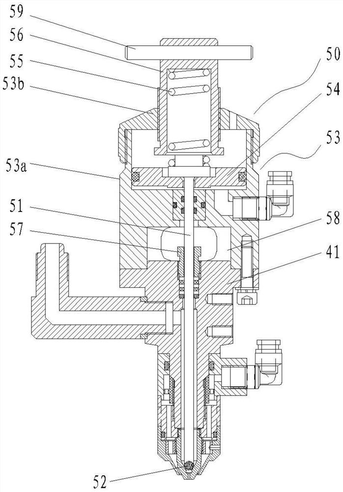
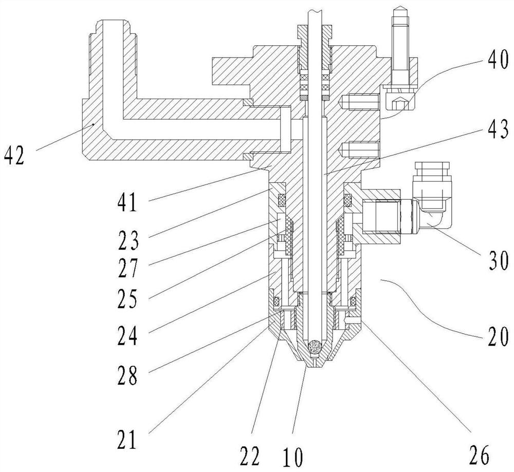
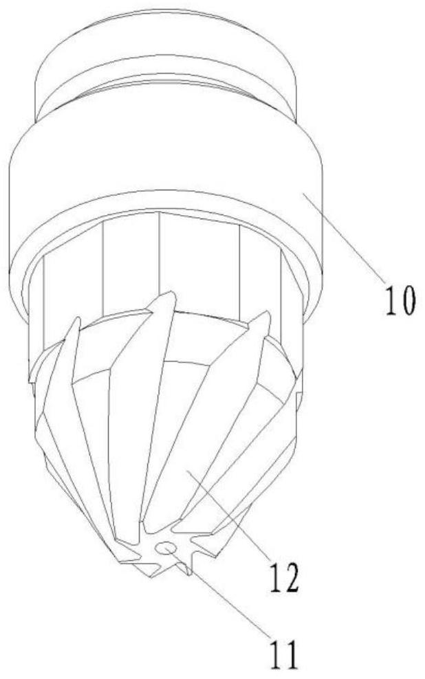
[0028] As shown in the figure, this embodiment provides a spiral glue-shaped glue valve, including a mandrel body 10, a jacket assembly 20 outside the mandrel body, an air supply head 30 arranged on the jacket assembly, and a valve core assembly 50. The lower end of the mandrel body extends downwards to the outside of the jacket assembly, an annular flow channel is formed between the mandrel body and the jacket assembly, the air supply head communicates with the annular flow channel, and the lower end of the mandrel body is provided with The extrusion port 11 for colloid extrusion, the center of the outer circular surface of the mandrel body is symmetrically provided with a plurality of drainage grooves 12, and each drainage groove is offset from top to bottom to the same circumferential direction of the mandrel body, and the drainage grooves are directed to the same circumferential direction of the mandrel body. Extending down to the lower end surface of the mandrel body, the ...


PUM


Abstract

The invention discloses a spiral glue-shaped gluing valve. The spiral glue-shaped gluing valve comprises a core shaft body, an outer sleeve component, an air supply head and a valve element assembly, wherein the outer sleeve component arranged outside the core shaft body in a sleeving mode, and the air supply head is arranged on the outer sleeve component; an annular flow channel is formed between the core shaft body and the outer sleeve component; an extrusion opening for extruding glue is formed in the lower end of the core shaft body. a plurality of drainage grooves are symmetrically formed in the center of the outer circle face of the core shaft body and extend downwards to the lower end face of the core shaft body; the lower ends of the drainage grooves are distributed around the extrusion opening in the circumferential direction so as to guide high-pressure airflow to flow to form spiral airflow; and the valve element component is used for opening or closing the extrusion opening. According to the spiral glue-shaped gluing valve, the spiral air flow is formed through guiding of the multiple spiral drainage grooves, so that the extruded glue is driven to form a spiral shape; reasonable space distribution of the glue is achieved through the spiral gluing technology; the glue is extruded after two to-be-bonded parts make contact; the glue is filled into a glue-free gap between spiral lines; the whole bonding space is filled with the glue; and therefore, the bonding effect is improved, and the bonding strength is improved.

Description

technical field [0001] The invention relates to the technical field of gluing, in particular to a spiral glue-shaped gluing valve. Background technique [0002] In automobile manufacturing, a large number of gluing processes are used to realize the connection of various parts. In the existing gluing process, a gluing valve is usually used for gluing. The outlet of the gluing valve is a cylindrical or elliptical cylindrical structure. , so the shape of the glue application can only form a cylindrical straight line or an elliptical straight line. Due to the single distribution structure of the glue in this glue application method, it is difficult to control the amount of glue applied to make the glue filled reasonably, so it is easy to cause glue overflow caused by excessive glue application , or insufficient bonding strength due to too little glue application, especially in the application process of hemming glue, the existing gluing valve is difficult to meet the use require...

Claims


Application Information

Patent Timeline
Patent Type & Authority Applications(China)
IPC IPC(8): B05C5/02B05C11/10
CPCB05C5/02B05C11/10B05C11/1002
Inventor 张德明
Owner CHONGQING CHANGJIANG COATING EQUIP
Why Eureka
Try Eureka