
Feeding equipment with impurity removal and anti-blocking functions for feed production

A technology of anti-blocking and tools, applied in the direction of feed, application, transportation and packaging, etc., can solve the problems of inability to remove debris, poor feeding, and blockage of the feeding pipe, so as to improve the dredging effect, smooth feeding, and avoid The effect of clogging

Pending Publication Date: 2021-10-22
武汉市新洲区万鹏饲料厂
View PDF15 Cites 2 Cited by
  • Summary
  • Abstract
  • Description
  • Claims
  • Application Information

AI Technical Summary

Problems solved by technology

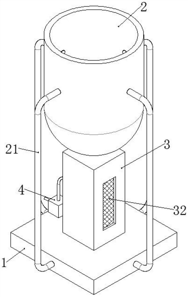
[0003] When producing feed, various raw materials need to be mixed, and then the mixed raw materials are prepared into granules. The granulated raw materials are generally output through the feeding equipment. The feeding equipment in the prior art is generally a funnel-shaped hopper. During the feeding process, a feeding pipe is installed at the bottom of the hopper, and feed particles may block the feeding pipe during the feeding process, resulting in poor feeding
[0004] At the same time, the granulation process of feed production may produce some debris, etc. The existing feeding equipment generally only has the function of feeding, and the debris cannot be removed at the same time during the feeding process, resulting in the feed pellets after feeding. It is directly packaged and needs to be transported to the impurity removal equipment for debris removal, resulting in an increase in feed production processes, an increase in equipment costs, and a decrease in the efficiency of feed production

Method used


Image

  • Feeding equipment with impurity removal and anti-blocking functions for feed production
  • Feeding equipment with impurity removal and anti-blocking functions for feed production
  • Feeding equipment with impurity removal and anti-blocking functions for feed production

Examples


Embodiment 1

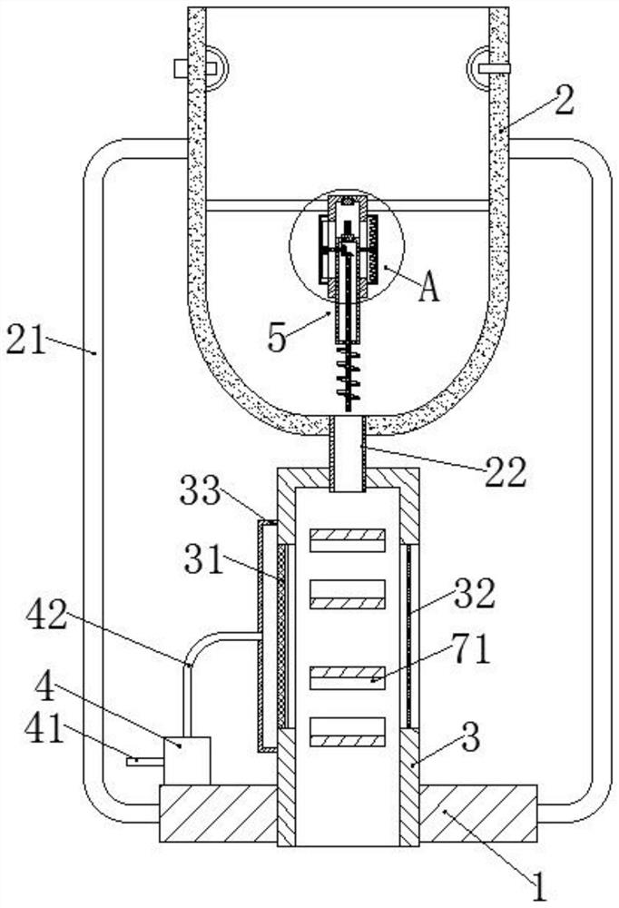
[0033] A feeding device for feed production with functions of removing impurities and preventing blocking, comprising a base 1, a hopper 2, a removing bin 3, a removing fan 4 and an anti-blocking device 5; the hopper 2 is located directly above the base 1, and the hopper 2 A support rod 21 is fixedly connected between the outer wall of the base and each side of the base 1, the lower part of the hopper 2 is arc-shaped, and the bottom of the hopper 2 is fixedly connected with a feeding pipe 22, and the impurity removal bin 3 is a cuboid cavity with an open bottom. structure, the bottom of the impurity removal bin 3 is fixed in the base 1, the center of the top plate of the impurity removal bin 3 is fixedly connected with the feeding pipe 22, and the left and right side plates of the impurity removal bin 3 are respectively fixed with the first filter screen 31 and the second Two filter screens 32, the outer wall of the left side plate of the miscellaneous bin 3 is fixedly connecte...

Embodiment 2

[0037] The difference from Example 1 is that it also includes the following:

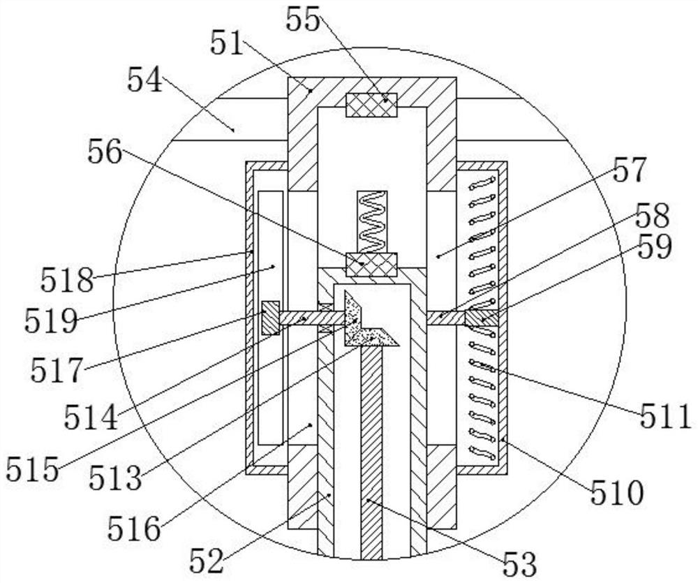
[0038] The anti-blocking device 5 includes a fixed cylinder 51, a lifting cylinder 52 and an anti-blocking rod 53; The inner wall of the fixed cylinder 51 is fixedly connected, the lower surface of the top plate of the fixed cylinder 51 is fixedly connected with an electromagnet 55, the electromagnet 55 is electrically connected with the external AC power supply, the lifting cylinder 52 is slidingly connected in the fixed cylinder 51, and the top surface of the lifting cylinder 52 is fixed Connected with the permanent magnet 56 corresponding to electromagnet 55, the front and rear side plates of fixed tube 51 and the right side plate are provided with the first chute 57, and the front and rear side plates of lifting tube 52 and the right side plate outer wall are fixedly connected with the first chute. The slide bar 58 corresponding to the chute 57 is slidably connected in the corresponding first ch...

Embodiment 3

[0042] The difference from Example 2 is that it also includes the following content:

[0043] The anti-blocking rod 53 is connected with the bottom plate of the lifting tube 52 in rotation, and the anti-blocking rod 53 below the lifting tube 52 is fixedly connected with a helical blade 512, and the top of the anti-blocking rod 53 is fixedly connected with a driven bevel gear 513, and the left side of the lifting tube 52 A shaft 514 is rotatably connected to the side plate, and the right end of the shaft 514 is fixedly connected with a driving bevel gear 515, the driving bevel gear 515 meshes with the driven bevel gear 513, and the left side plate of the fixed cylinder 51 is provided with a second chute 516 The shaft 514 is slidably connected in the second chute 516, the left end of the shaft 514 is fixedly connected with the driving gear 517, the outer wall of the left side plate of the fixed cylinder 51 is fixedly connected with the transmission box 518, and the inner wall of ...


PUM


Abstract

The invention discloses feeding equipment with impurity removal and anti-blocking functions for feed production. The feeding equipment comprises a base, a hopper, an impurity removal bin, an impurity removal fan and an anti-blocking device, wherein the anti-blocking device comprises a fixed cylinder, a lifting cylinder and an anti-blocking rod. Feed particles enter the hopper and enter the impurity removal bin through a feeding pipe, in the feeding process, through the arrangement of the anti-blocking device, the phenomenon that the feeding pipe is blocked can be avoided, feeding is smoother, in the falling process of feeds in the impurity removal bin, the impurity removal fan extracts external air through an air inlet pipe and conveys the air into a fan cover through an air outlet pipe, then the air is blown into the impurity removal bin through a first filter screen, chippings can be blown out through a second filter screen, and therefore the impurity removal function is achieved; and the second filter screen can also intercept the feed particles in the impurity removal bin, so that the feed particles can smoothly fall down from the bottom of the impurity removal bin.

Description

technical field [0001] The invention relates to the technical field of feed production equipment, in particular to a feeding equipment for feed production with functions of removing impurities and preventing blockage. Background technique [0002] Feed is the general term for the food of animals raised by all people. In a narrower sense, general feed mainly refers to the food of animals raised in agriculture or animal husbandry. Feed includes soybeans, soybean meal, corn, fish meal, amino acids, miscellaneous meal, whey powder , oil, meat and bone meal, grains, feed additives and more than ten varieties of feed raw materials. [0003] When producing feed, various raw materials need to be mixed, and then the mixed raw materials are prepared into granules. The granulated raw materials are generally output through the feeding equipment. The feeding equipment in the prior art is generally a funnel-shaped hopper. During the feeding process, a feeding pipe is installed at the bot...

Claims


Application Information

Patent Timeline
Patent Type & Authority Applications(China)
IPC IPC(8): B65G65/46B65G47/74A23N17/00B07B9/00B07B4/02
CPCB65G65/463B65G47/74A23N17/00B07B9/00B07B4/02
Inventor 汪桃荣
Owner 武汉市新洲区万鹏饲料厂
Learn More