
Excavator movable arm energy recovery system based on pressure variable energy accumulator

A technology of energy recovery and accumulators, which is applied to mechanically driven excavators/dredgers, earth movers/shovels, construction, etc., can solve the problem of inability to directly release the boom cylinder, energy cannot be recovered, and energy recovery Problems such as low utilization rate, to achieve the effect of reducing requirements, reducing energy loss, and reducing heat generation

Active Publication Date: 2021-10-22
HEFEI UNIV OF TECH
View PDF7 Cites 0 Cited by
  • Summary
  • Abstract
  • Description
  • Claims
  • Application Information

AI Technical Summary

Problems solved by technology

[0004] The present invention aims to overcome the deficiencies of the prior art, and proposes an energy recovery system for excavator arms based on variable pressure accumulators. Matching is carried out to solve the problem of low energy recovery utilization rate when the accumulator pressure is too low and the energy cannot be recovered when the accumulator pressure is too high, and at the same time solve the problem that the oil in the accumulator cannot be directly released to the boom cylinder under some working conditions problem, and by controlling the air pressure of the gas in the piston accumulator, the speed at which the boom can be lowered or raised can be controlled

Method used


Image

  • Excavator movable arm energy recovery system based on pressure variable energy accumulator
  • Excavator movable arm energy recovery system based on pressure variable energy accumulator

Examples


Embodiment Construction

[0019] The preferred embodiments of the present invention will be described in detail below in conjunction with the accompanying drawings, so that the advantages and features of the present invention can be more easily understood by those skilled in the art, so as to define the protection scope of the present invention more clearly.

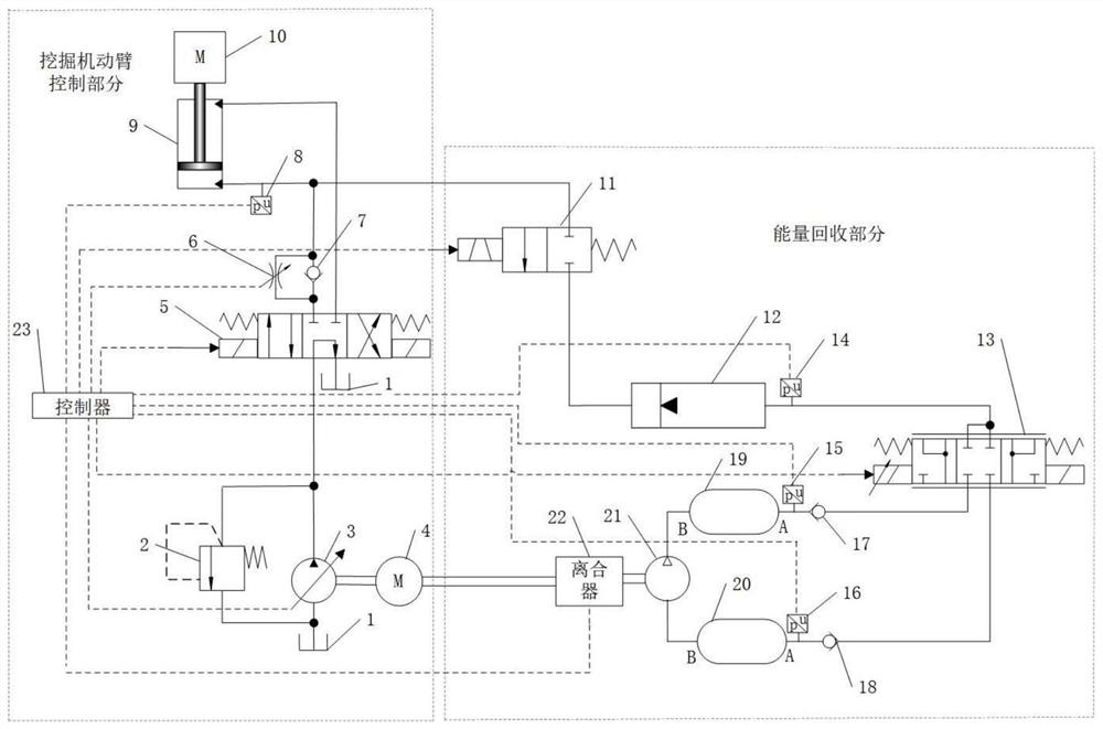
[0020] see figure 1 An energy recovery system for an excavator arm based on a variable pressure accumulator mainly includes an excavator arm control part and an energy recovery part. The boom control unit is mainly composed of fuel tank 1, overflow valve 2, hydraulic variable pump 3, engine 4, three-position four-way reversing valve 5, adjustable throttle valve 6, hydraulic check valve 7, first pressure sensor 8, dynamic The arm cylinder 9 and the controller 23 are composed, and the energy recovery part is mainly composed of the on-off valve 11, the piston accumulator 12, the pneumatic servo valve 13, the second pressure sensor 14, the third pres...


PUM


Abstract

The invention discloses an excavator movable arm energy recovery system based on a pressure variable energy accumulator. The excavator movable arm energy recovery system comprises a switch valve, the piston type energy accumulator, a pneumatic servo valve, a high-pressure air storage tank, a low-pressure air storage tank, an air pump, a first pneumatic one-way valve and a second pneumatic one-way valve; an oil port of the piston type energy accumulator is connected with a movable arm oil cylinder through the switch valve, an inflation port of the piston type energy accumulator is connected with two air outlets of the pneumatic servo valve at the same time, two air inlets of the pneumatic servo valve are connected with the air outlet end of the high-pressure air storage tank and the air inlet end of the low-pressure air storage tank through pneumatic one-way valves respectively, and an air outlet of the high-pressure air storage tank is connected with an air inlet of the low-pressure air storage tank. Energy is recovered through the piston type energy accumulator, the high-pressure air storage tank and the low-pressure air storage tank, and the pressure of an air cavity of the piston type energy accumulator is controlled through the high-pressure air storage tank and the low-pressure air storage tank, so that descending of a movable arm during energy recovery and ascending of the movable arm during energy release are controlled, and energy recovery under various working conditions is achieved.

Description

technical field [0001] The invention relates to the technical field of an excavator arm energy recovery system, in particular to an excavator arm energy recovery system based on a variable pressure accumulator. Background technique [0002] Since the 20th century, the problems of energy shortage and environmental pollution have become more and more serious, and all countries have put the reduction of greenhouse gas emissions and environmental protection on the agenda. Among all construction machinery, the greenhouse gas emissions brought by excavators account for a large part, so the research and application of energy-saving technology for excavators is particularly necessary. [0003] The traditional way of recovering the potential energy of the boom by directly connecting the accumulator to the rodless chamber of the boom cylinder puts forward higher requirements on the parameter matching of the accumulator. Too low pressure of the accumulator will reduce the energy recove...

Claims


Application Information

Patent Timeline
IPC IPC(8): E02F9/20E02F9/22E02F9/26E02F3/38E02F3/42
CPCE02F9/2025E02F9/2217E02F9/2267E02F9/2292E02F9/264E02F3/38E02F3/42
Inventor 曾亿山吕安庆刘常海高干虢锐
Owner HEFEI UNIV OF TECH
Features
  • Generate Ideas
  • Intellectual Property
  • Life Sciences
  • Materials
  • Tech Scout
  • Unparalleled Data Quality
  • Higher Quality Content
  • 60% Fewer Hallucinations
Learn More