
Integrated center backdraft condensation vacuum hot water boiler

A hot water boiler and vacuum furnace technology, applied in the field of oil-fired gas boilers, can solve the problems of unfavorable high-temperature flue gas accumulation, low surface heat transfer coefficient, waste of latent heat resources, etc., and achieve the goals of facilitating residents' water use, protecting the environment, and reducing energy consumption Effect

Pending Publication Date: 2021-10-22
浙江大工新能源有限公司
View PDF0 Cites 0 Cited by
  • Summary
  • Abstract
  • Description
  • Claims
  • Application Information

AI Technical Summary

Problems solved by technology

[0004] The front smoke box of the existing boiler is a dry back structure surrounded by the front tube plate, front door cover and connecting plate. The temperature inside the front smoke box of the positive pressure combustion boiler can reach more than 800 °C; currently all oil-fired gas boilers use smoke tubes The structure, that is, the flue gas travels in the pipe, the flue gas washes the heat exchange surface of the flue pipe longitudinally, and the surface heat transfer coefficient is low; at the same time, the existing central combustion boiler transfer chamber is generally a dry back structure, and the high-temperature flue gas is in the transfer chamber In the process of conveying to the heat exchanger, no guiding structure is designed, which is not conducive to the accumulation of high-temperature flue gas inside the heat exchanger, resulting in generally low heat exchange efficiency, and the waste of latent heat resources carried in high-temperature flue gas is serious. low rate

Method used


Image

  • Integrated center backdraft condensation vacuum hot water boiler
  • Integrated center backdraft condensation vacuum hot water boiler
  • Integrated center backdraft condensation vacuum hot water boiler

Examples


Embodiment Construction

[0031] The technical solutions of the present invention will be further described below in conjunction with the accompanying drawings and through specific implementation methods.

[0032] Wherein, the accompanying drawings are only for illustrative purposes, showing only schematic diagrams, rather than physical drawings, and should not be construed as limitations on this patent; in order to better illustrate the embodiments of the present invention, some parts of the accompanying drawings will be omitted, Enlarged or reduced, does not represent actual product size.

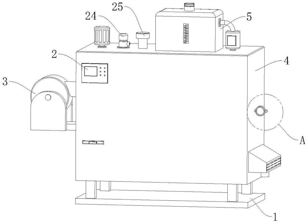
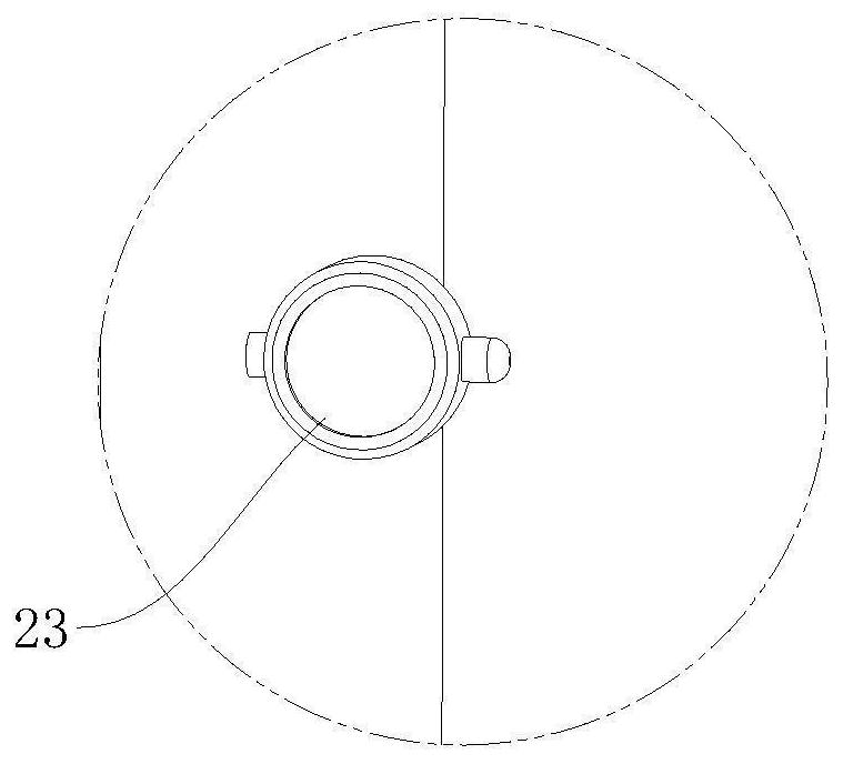
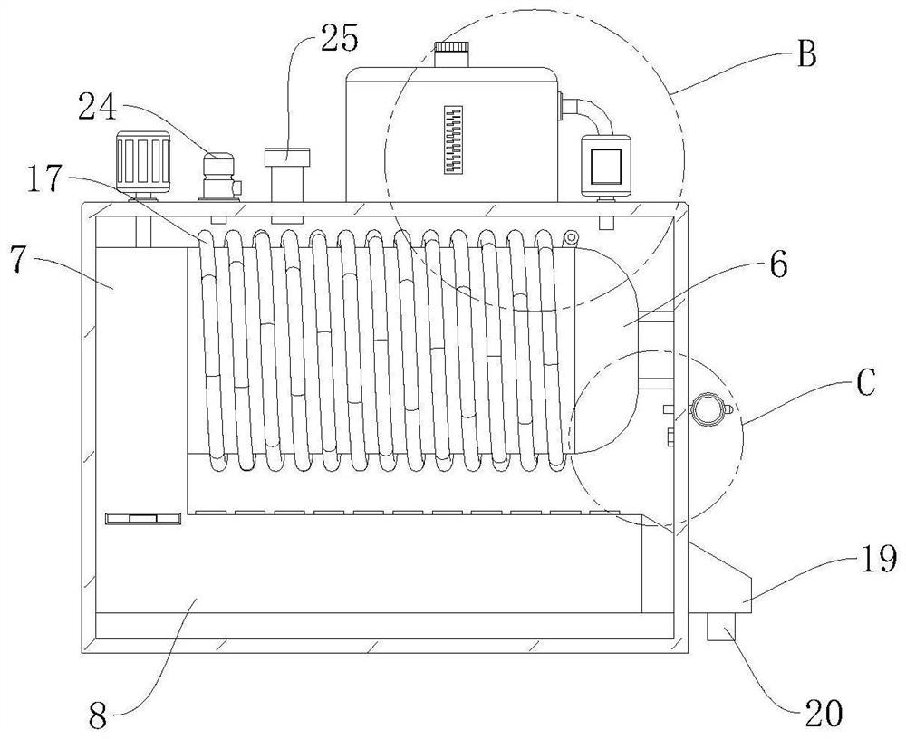
[0033] refer to Figure 1 to Figure 8 The one-piece central backfiring condensing vacuum hot water boiler shown includes a base 1, which is arranged horizontally, and also includes a controller 2, a burner 3, a vacuum furnace 4 and a backfiring mechanism 5. The vacuum The furnace 4 is fixed on the top of the base 1 through four symmetrically arranged support rods, and the vacuum furnace 4 is a rectangular shell s...


PUM


Abstract

The invention relates to the technical field of oil and gas boilers, in particular to an integrated center backdraft condensation vacuum hot water boiler which comprises a base and further comprises a controller, a burner, a vacuum furnace and a backdraft mechanism, wherein the vacuum furnace is of a rectangular shell structure, the burner is fixedly arranged on one side wall of the vacuum furnace, the backdraft mechanism is arranged in the vacuum furnace and used for improving the heat exchange efficiency, the backdraft mechanism comprises a furnace pipe, a smoke guide chamber, a box type heat exchanger, a water supply assembly and a guide assembly, and the burner, the water supply assembly and the guide assembly are all electrically connected with the controller. The integrated center backdraft condensation vacuum hot water boiler can replace longitudinal scouring smoke pipe heat exchange surfaces, so that the surface heat exchange coefficient is increased, and meanwhile, high-temperature smoke can be conveniently and rapidly conveyed to the heat exchanger from the smoke guide chamber, so that the heat exchange speed is increased; latent heat resources carried in the high-temperature smoke are fully utilized, so that resource waste is effectively avoided.

Description

technical field [0001] The invention relates to the technical field of fuel-fired gas boilers, in particular to an integrated central backfiring condensing vacuum hot water boiler. Background technique [0002] Oil-fired gas boilers, as the name implies, refer to boilers that can both fuel oil and gas. There was no such dual-fuel boiler before, because the burners were either oil or gas, and there were no dual-fuel burners. With the rapid development of thermal energy equipment in the world, some countries in Europe have begun to produce and sell oil-fired gas burners. The organic combination of dual-fuel burners and boilers has given birth to a new type of boiler - oil-fired gas boilers. boiler. [0003] With the development of the national economy and the improvement of people's living standards, the energy consumption structure occupies a pivotal position in economic development. At present, coal-fired domestic and industrial boilers that are widely used and widely dis...

Claims


Application Information

Patent Timeline
IPC IPC(8): F24H8/00F24H9/18F24H9/20F23J15/06
CPCF24H8/00F24H9/18F24H9/20F23J15/06Y02E20/30Y02B30/00
Inventor 李志军
Owner 浙江大工新能源有限公司
Learn More