
Sintering method for reducing content of NOx in sintering flue gas in ignition stage

A technology of sintering flue gas and sintering method, applied in the field of sintering, which can solve the problems of lowering flame temperature, unfavorable sintering production, limited space and operation, etc., and achieves the effect of prolonging ignition time, improving sintering ignition layout, and improving surface quality

Active Publication Date: 2021-10-22
ANGANG STEEL CO LTD
View PDF10 Cites 0 Cited by
  • Summary
  • Abstract
  • Description
  • Claims
  • Application Information

AI Technical Summary

Problems solved by technology

Patent Nos. CN201710416516.8, CN201720657521.3 and CN201820782346.5 introduce the use of pre-mixing technology for the burner to adjust the mixing of air and gas so that it can be fully completed in one mixing, thereby reducing the flame length and increasing the flame intensity. The flame temperature is reduced, and finally the concentration of NOx in the combustion flue gas is reduced; patent numbers CN201610982181.1 and CN201811161162.8 use the addition of CaO-based additives during sintering to reduce the temperature of the combustion layer during the sintering process and reduce the combustion temperature , which deteriorates the NOx production environment, and finally improves the quality of sintering flue gas; but there are two problems with the above measures. First, the on-site sintering section is limited by space and operation, and the burner is a combustion system with only primary air, which does not have The feasibility of adjusting the flame length and increasing the mixing time of primary empty coal. Secondly, adding CaO to make it adhere to the fuel during sintering can reduce the contact between N and O and lower the ambient temperature, but the combustion efficiency of fuel is reduced, which is not conducive to sintering production

Method used


Image

  • Sintering method for reducing content of NOx in sintering flue gas in ignition stage
  • Sintering method for reducing content of NOx in sintering flue gas in ignition stage
  • Sintering method for reducing content of NOx in sintering flue gas in ignition stage

Examples


Embodiment Construction

[0021] The present invention will be described in more detail through examples below. These examples are only descriptions of the best implementation modes of the present invention, and do not limit the scope of the present invention in any way.

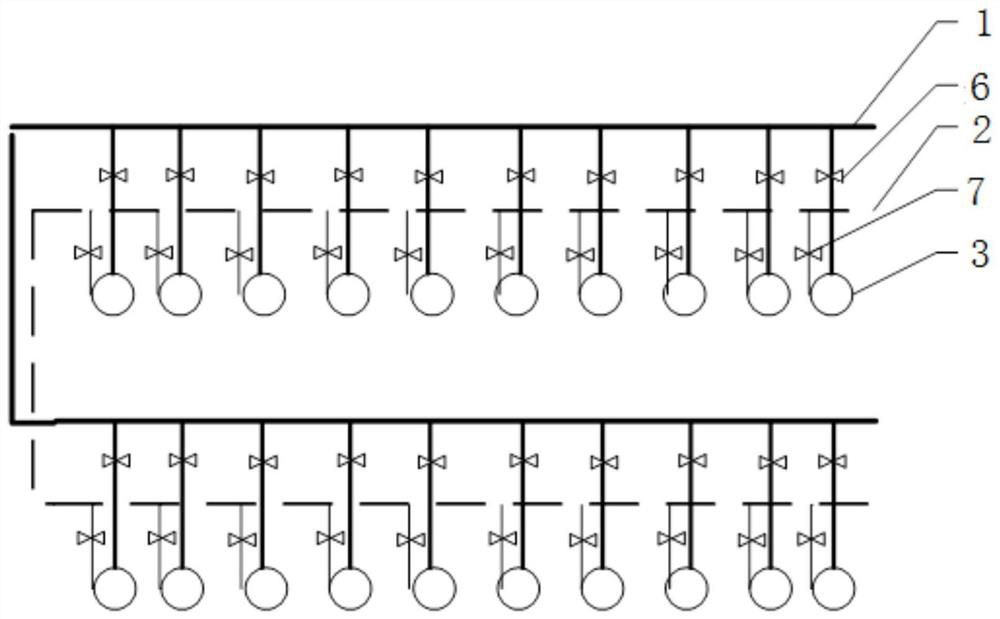
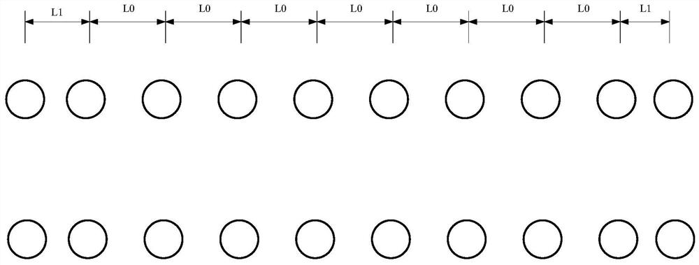
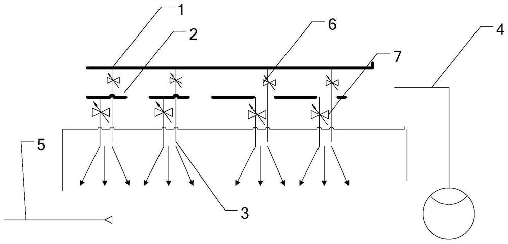
[0022] See image 3 , Figure 4 , the sintering igniter includes air main pipe 1, gas main pipe 2, ignition burner 3, infrared thermal image temperature detection system 4, air gas flow control system 5, air valve 6, gas valve 7; air main pipe 1 and gas main pipe 2 come from The air and gas enter the ignition burner 3 to be ignited, and the infrared thermal imaging temperature detection system 4 measures the temperature of each row of burners, judges the temperature signal and transmits the signal to the air gas flow control system 5, and the air gas flow control system 5 Control the air valve 6 and the gas valve 7 to adjust the flow and air-fuel ratio.

[0023] A sintering method for reducing the NOx content in the sintering flue ...


PUM


Abstract

The invention relates to a sintering method for reducing the content of NOx in sintering flue gas in an ignition stage. The flame temperature is reduced to 1100-1200 DEG C from the traditional 1200-1300 DEG C by reducing the flame temperature of a sintering igniter and prolonging the sintering ignition time, and the ignition temperature measured by a thermocouple is reduced to 850 + / -50 DEG C from 950 + / -50 DEG C, so that a temperature interval in which thermal fuel is prone to generating the NOx is avoided, and the content of nitric oxide in the sintering flue gas is reduced. After the method is implemented, the content of the NOx in the flue gas of the sintering ignition stage is reduced to about 210 ppm from original 300 ppm and is reduced by 90 ppm, and in addition, the consumption of sintering ignition gas is reduced to 0.090 GJ / t sinter from original 0.092 GJ / t sinter.

Description

technical field [0001] The invention relates to the field of sintering, in particular to a sintering method capable of reducing the NOx content in the sintering flue gas at the ignition stage. Background technique [0002] Ignition is an important part of sintering production. In order to prevent the occurrence of raw material or insufficient ignition, the ignition temperature is generally required to be 950±50°C (flame front temperature 1200-1300°C), and the ignition guns are arranged in two rows in a horizontal line. The distribution and ignition temperature are relatively high, and even sintering slight positive pressure ignition occurs, and the ignition time is 1.5-3min. However, in actual production, the NOx content in the flue gas in the ignition section is higher than that in other parts of the trolley. For example, the NOx in the ignition section is about 300ppm, and it will be reduced to 120ppm in the later stage, and even reduced to 50ppm at the end of sintering. T...

Claims


Application Information

Patent Timeline
Patent Type & Authority Applications(China)
IPC IPC(8): F27D17/00F27D19/00
CPCF27D17/008F27D19/00
Inventor 任伟王亮韩子文张伟国泉峰王小强刘沛江胡邵磊李晓春
Owner ANGANG STEEL CO LTD
Learn More