Electrically-controlled resonant coupled artificial surface plasmon cascade slow light device

An artificial surface plasmon and resonant coupling technology, applied in optical components, optics, instruments, etc., can solve problems such as lack of combination, uncontrollability, and single function, and achieve strong practicability, low power consumption, and enhanced binding capabilities Effect

Active Publication Date: 2021-10-22
SHANXI DATONG UNIV
View PDF5 Cites 1 Cited by
  • Summary
  • Abstract
  • Description
  • Claims
  • Application Information

AI Technical Summary

Problems solved by technology

[0009] To sum up, the existing slow-light devices are still making breakthroughs in the basic way, lacking the combination with other devices, resulting in the singleness and uncontrollability of functions

Method used


Image

  • Electrically-controlled resonant coupled artificial surface plasmon cascade slow light device
  • Electrically-controlled resonant coupled artificial surface plasmon cascade slow light device
  • Electrically-controlled resonant coupled artificial surface plasmon cascade slow light device

Examples


Embodiment 1

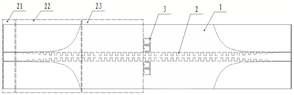
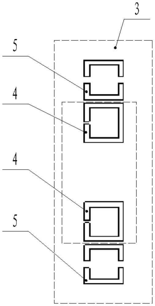
[0055] figure 1 It is a structural schematic diagram of an artificial surface plasmon cascaded slow light device provided by the present invention; such as figure 1 As shown, an electrically controlled resonantly coupled artificial surface plasmon cascade slow light device, comprising: a dielectric substrate 1 on which an artificial surface plasmon transmission line 2 is printed; the artificial surface At least one group of functional units 3 is provided in the transmission direction of the plasmon transmission line 2; each group of functional units 3 includes: pairs of bright and dark mode resonant structures symmetrically distributed on both sides of the transmission direction of the artificial surface plasmon transmission line 2, the The bright and dark mode resonant structure pair includes: the bright mode resonant structure arranged on the inside, and the dark mode resonant structure arranged on the outside; the dark mode resonant structure is provided with a PIN diode, a...

Embodiment 2

[0068] On the basis of Embodiment 1, an electrically controlled resonantly coupled artificial surface plasmon cascaded slow light device,

[0069] The artificial surface plasmon transmission line 2 includes: a feeding end transmission line and a receiving end transmission line;

[0070] The transmission line at the feeding end and the transmission line at the receiving end have the same structure and are symmetrical based on the center;

[0071] The feeding end transmission line includes: a coplanar waveguide structure 21 , a matching transition structure 22 and a double-sided corrugated waveguide strip structure 23 arranged in sequence along the transmission direction of the artificial surface plasmon transmission line 2 .

[0072] Figure 5 is a structural schematic diagram of the coplanar waveguide structure of the present invention; Figure 6 is a structural schematic diagram of a matching transition structure in the present invention; Figure 7 is a structural schemati...


PUM


Abstract

The invention provides an electrically-controlled resonant coupled artificial surface plasmon cascaded slow light device, which comprises a dielectric substrate which is printed with an artificial surface plasmon transmission line; at least one group of functional units are arranged in the transmission direction of the artificial surface plasmon transmission line; each group of function units comprises bright and dark mode resonance structure pairs symmetrically distributed on two sides of the transmission direction of the artificial surface plasmon transmission line, and each bright and dark mode resonance structure pair comprises a bright mode resonance structure arranged on the inner side and a dark mode resonance structure arranged on the outer side; a PIN diode is arranged on the dark mode resonance structure, and mutual coupling between the dark mode resonance structure and the dark mode resonance structure is controlled by controlling the on-off state of the PIN diode, so that the group velocity and the propagation characteristic of the artificial surface plasmon are changed; the invention has the beneficial effect of dynamic tuning, and is suitable for the field of slow light devices.

Description

technical field [0001] The invention relates to the technical field of slow light devices, in particular to an electrically controlled resonance coupled artificial surface plasmon cascade slow light device. Background technique [0002] Slow light refers to the phenomenon that light propagates in the medium at a slower group velocity under certain specific conditions and medium structures. It is considered to be the most potential of all-optical communication and quantum information processing technology to realize the functions of optical cache and optical switch. In the prior art, a special structure is designed to achieve slow light by changing the dispersion coefficient of the material or starting from the structure of the material, but the use value of the solution is limited due to the fixed structure. [0003] Since slow light enhances the light intensity, another very important application of slow light is to enhance the interaction between light and matter per unit ...

Claims


Application Information

Patent Timeline
Patent Type & Authority Applications(China)
IPC IPC(8): G02B5/00
CPCG02B5/008
Inventor 苏晓强董丽娟贺佳俊黄宇聪邓富胜刘艳红石云龙
Owner SHANXI DATONG UNIV
Why Eureka
Try Eureka