Modeling method for cutting force of micro PCD milling cutter without side edge relief angle

A technology of milling tools and modeling methods, applied in CAD numerical modeling, special data processing applications, complex mathematical operations, etc. Quality, the effect of improving processing efficiency

Pending Publication Date: 2021-10-22
BEIJING INSTITUTE OF TECHNOLOGYGY
View PDF1 Cites 5 Cited by
  • Summary
  • Abstract
  • Description
  • Claims
  • Application Information

AI Technical Summary

Problems solved by technology

At present, there is a lack of research on cutting force modeling of micro-PCD milling tools without side edges, and ...

Method used


Image

  • Modeling method for cutting force of micro PCD milling cutter without side edge relief angle
  • Modeling method for cutting force of micro PCD milling cutter without side edge relief angle
  • Modeling method for cutting force of micro PCD milling cutter without side edge relief angle

Examples


Embodiment Construction

[0072] The present invention will be further described below in conjunction with accompanying drawing.

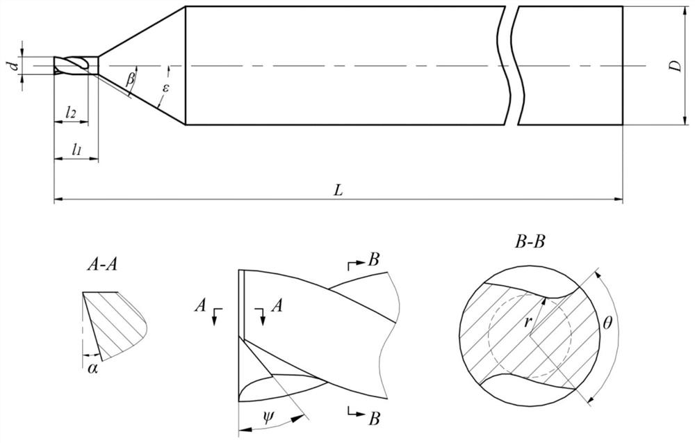
[0073] With reference to the accompanying drawings, a schematic diagram of a micro-PCD milling tool without side edges is shown as figure 1 As shown, when the milling tool is processed, the traditional milling process is performed by the cutting edge, and the abrasive grains on the flank face are ground, so milling force and grinding force are generated.

[0074] The cutting force modeling method of a kind of micro PCD milling cutter without side edge that the present invention proposes, comprises the following steps:

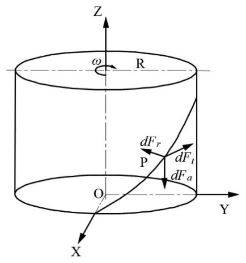
[0075] Step S1, establish the tool coordinate system

[0076] established as figure 2 In the tool coordinate system shown, the positive direction of the X-axis is the feed direction, the positive direction of the Z-axis is the direction of the tool axis, and the positive direction of the Y-axis is the direction following the right-handed Cartesian coordin...


PUM


Abstract

The invention belongs to the technical field of micro cutter machining, and provides a side-edge-relief-angle-free micro PCD milling cutter cutting force modeling method which mainly comprises the steps: S1, establishing a cutter coordinate system; s2, defining an infinitesimal radial force dFrj, an infinitesimal tangential force dFtj and an infinitesimal axial force dFaj of a point P on the cutting edge of the cutter at any moment and a radial grinding force dFnj and a tangential grinding force dFfj of a rear cutter surface; s3, determining a cut-in angle and a cut-out angle of a milling cutter; s4, establishing infinitesimal cutting force expressions of the milling cutter in the X, Y and Z directions under the rectangular coordinate system; s5, determining the contact state of the cutting edge and the workpiece; s6, obtaining cutting force models of the milling cutter in the X, Y and Z directions through numerical integration. The model can predict the cutting force of the milling cutter under different main shaft rotating speeds, feeding speeds and radial cutting depths, and then the main shaft rotating speeds, the feeding speeds and the radial cutting depths can be optimized, so that the purposes of reducing cutter abrasion and improving the machining efficiency and the machining quality are achieved.

Description

technical field [0001] The invention relates to a tool cutting force modeling method, in particular to a cutting force modeling method for a micro PCD milling tool without a side edge, and belongs to the technical field of micro tool processing. Background technique [0002] With the rapid development of advanced manufacturing industry, industrial products tend to be miniaturized gradually, and tiny parts are more and more widely used in aviation, aerospace, power, electronics, precision instruments and other fields. Advanced manufacturing technologies such as micro-milling are the main methods for manufacturing tiny parts. However, these tiny parts are mostly made of cemented carbide, ceramics (zirconia), titanium alloys, carbon fiber / metal matrix composites, high-silicon aluminum alloys and easy-to-adhesive tools. Non-ferrous metals and other materials, these materials are very easy to cause problems such as tool wear and failure during processing, which in turn affects th...

Claims


Application Information

Patent Timeline
IPC IPC(8): G06F30/20G06F17/13G06F119/14G06F111/10
CPCG06F30/20G06F17/13G06F2119/14G06F2111/10
Inventor 梁志强陈锐袁昊杜宇超马悦栾晓圣周天丰王西彬赵斌刘志兵
Owner BEIJING INSTITUTE OF TECHNOLOGYGY
Why Eureka
Try Eureka