
Fuel cell system

A fuel cell system and stack technology, applied in fuel cells, fuel cell additives, fuel cell heat exchange, etc., can solve the problems of reducing the power density of fuel cell systems, low fuel cell systems, and high power consumption of air compressors. , to achieve the effect of light weight, reduced power consumption and improved efficiency

Pending Publication Date: 2021-10-22
BEIJING SINOHYTEC
View PDF0 Cites 0 Cited by
  • Summary
  • Abstract
  • Description
  • Claims
  • Application Information

AI Technical Summary

Problems solved by technology

The disadvantage of the air compressor of the existing fuel cell system is that the power consumption of the air compressor is large, and the air compressor in the fuel cell system is powered by boosting DCDC or the power battery of the vehicle, and the air compressor will consume a large amount of energy output by the fuel cell. The power of the fuel cell system is low; at the same time, the volume and weight of the air compressor driven by the conventional motor are large, which reduces the power density of the fuel cell system

Method used


Image

  • Fuel cell system

Examples


Embodiment Construction

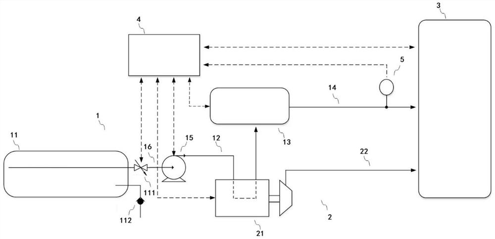
[0014] figure 1 and the following description describe alternative embodiments of the invention to teach those skilled in the art how to make and reproduce the invention. In order to teach the technical solutions of the present invention, some conventional aspects have been simplified or omitted. Those skilled in the art should understand that modifications or substitutions from these embodiments will fall within the protection scope of the present invention. Those skilled in the art will appreciate that the features described below can be combined in various ways to form multiple variations of the invention. As such, the invention is not limited to the alternative embodiments described below, but only by the claims and their equivalents.

[0015] figure 1 A block diagram of a fuel cell system according to one embodiment of the present invention is shown. Such as figure 1 As shown, the fuel cell system includes a hydrogen assembly 1, an air assembly 2 and an electric stac...


PUM


Abstract

The invention provides a fuel cell system, and the system comprises a hydrogen assembly, an air assembly and a galvanic pile; the air assembly comprises an air compressor and an air pipeline, and the hydrogen assembly comprises a first pipeline for conveying liquid hydrogen; the air compressor is driven by a superconducting motor, and the air compressor is communicated with an air inlet of the galvanic pile through the air pipeline; the hydrogen assembly is communicated with a hydrogen inlet of the galvanic pile, the hydrogen assembly vaporizes liquid hydrogen and then sends the liquid hydrogen into the galvanic pile, and the first pipeline is connected with a cooling pipeline of the air compressor so that the liquid hydrogen in the first pipeline can enable a superconducting motor of the air compressor to be cooled to the working temperature. The fuel cell system has the advantages that the low-temperature characteristic of liquid hydrogen is effectively utilized; the net output power is improved; and the power density of the fuel cell system is improved.

Description

technical field [0001] The present invention relates to the field of fuel cell vehicles, in particular to a fuel cell system. Background technique [0002] A hydrogen fuel cell is a power generation device that directly converts the chemical energy generated by the reaction of hydrogen and oxygen into electrical energy through an electrochemical reaction. It has the advantages of high power generation efficiency and low environmental pollution, so it is widely used in the automotive field. The fuel cell includes an auxiliary system composed of air compressors, water pumps, booster DCDC and other components to assist its operation. The power consumption of the auxiliary system affects the net output of the fuel cell system. The air compressor of the fuel cell is usually driven by a motor, and the power of the air compressor accounts for about 80% of the total power of the auxiliary system. Therefore, reducing the power consumption of the air compressor can greatly increase th...

Claims


Application Information

Patent Timeline
Patent Type & Authority Applications(China)
IPC IPC(8): H01M8/04007H01M8/04029H01M8/04082H01M8/04089H01M8/0438H01M8/04701
CPCH01M8/04029H01M8/04089H01M8/04201H01M8/04074H01M8/04738H01M8/04388Y02E60/50H01M8/04208
Inventor 李鹏伟张国强贾能铀杨绍军张禾
Owner BEIJING SINOHYTEC
Learn More