Multi-element copper alloy up-drawing furnace and drawing casting method

A copper alloy, multi-component technology, applied in the field of multi-component copper alloy upper induction furnace and casting, can solve the problems of internal stress, increased probability of fragmentation, and shortened service life of upper lead molds, so as to prolong the service life and slow down graphite burning Damage, reduce the effect of the chance of fragmentation

Active Publication Date: 2021-10-26
东莞市凤岗冠铸铜业有限公司
View PDF14 Cites 2 Cited by
  • Summary
  • Abstract
  • Description
  • Claims
  • Application Information

AI Technical Summary

Problems solved by technology

However, the output of the vacuum furnace is small and the production cost is high
In addition, as described in CN202524583U, the inner cavity of the furnace is divided into a melting chamber and an upper induction chamber, the melting chamber and the upper induction chamber are connected through a melting channel, and graphite plates are used to form a melting pool. The following technical problems exist in actual production: The metal in the melting furnace is continuously melted through the melting channel. When the height of the molten metal rises to about half of the height of the inner cavity of the molten pool, the inner lining is heated unevenly from top to bottom, causing internal stress and increasing the probability of fragmentation.
[0005] In addition, copper alloys are produced by upward drawing, and the types of alloys increase, and the strength of copper condensed by upward drawing increases. Graphite, as the inner core of the upper drawing mold, has a good lubricating effect, but the graphite inner core has poor wear resistance and serious wear and tear. Compared with the pure copper up-leading process, the service life of the up-leading die is significantly shortened

Method used


Image

  • Multi-element copper alloy up-drawing furnace and drawing casting method
  • Multi-element copper alloy up-drawing furnace and drawing casting method
  • Multi-element copper alloy up-drawing furnace and drawing casting method

Examples


Embodiment 1

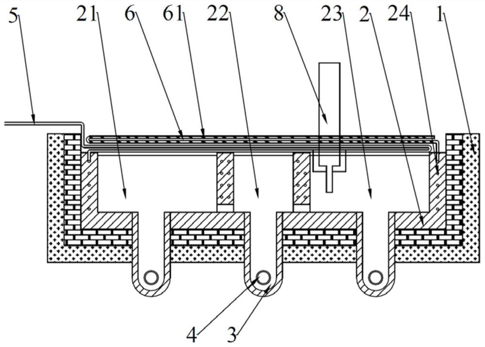
[0059] The graphite molten pool 2 size of embodiment 1, embodiment 4, comparative example 1, comparative example 2 is that molten pool inner cavity is long 5.397m, wide 0.4m, high 0.5m; Melted pool side wall thickness 150mm, bottom wall thickness 150mm; The inner diameter of the trench is 580mm, and the inner diameter of the inert gas channel 24 in Example 1 is 8mm; the volume ratio of the melting chamber 21, the transition chamber 22 and the upper induction chamber 23 in the side-by-side direction is 2.179:1:2.218. The graphite molten pool 2 size of embodiment 2 and embodiment 3 is the same as embodiment 1.

Embodiment 2

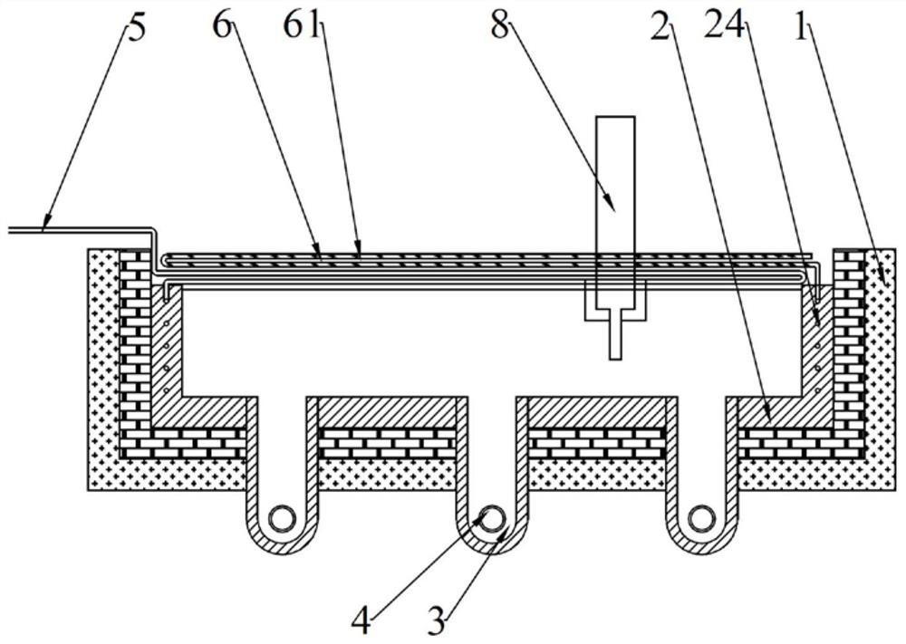
[0061] Such as figure 2 As shown, embodiment 2 is based on embodiment 1, the difference is that no separator 3 is provided in the graphite molten pool 2, and the inert gas passages 24 are spirally wound around the side walls of the graphite molten pool.

Embodiment 3

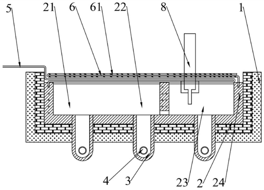
[0063] Such as image 3 As shown, embodiment 3 is based on embodiment 1, the difference is that graphite molten pool 2 is provided with a partition 3, and the position of partition 3 is the same as that of partition 3 between transition chamber 22 and upper introduction chamber 23 in embodiment 1 The clapboard 3 separates the inner cavity of the graphite melting pool 2 into a melting cavity 21 and an upper lead cavity 23, two inner circulation melting grooves 3 are arranged in the melting cavity 21, and one inner circulation melting groove is arranged in the upper leading cavity 3. The inert gas channel 24 is arranged in the side wall and the partition of the graphite melting pool, and is arranged spirally in the side wall of the melting chamber 21 and the upper induction chamber 23 respectively.


PUM


Abstract

The invention discloses a multi-element copper alloy up-drawing furnace. The multi-element copper alloy up-drawing furnace comprises a furnace shell and a heating unit, wherein an open graphite molten pool is formed in the furnace shell, and a molten passage is formed in the bottom of the graphite molten pool; the heating unit is used for heating the melting passage; an inert gas passage is arranged in the wall of the graphite molten pool, and a gas inlet of the inert gas passage is connected with a preheating gas source. According to the multi-element copper alloy up-drawing furnace, the graphite molten pool in the multi-element copper alloy up-drawing furnace can prevent impurities from being introduced into alloy molten liquid; by arranging the inert gas passage, inert gas is introduced for protection when a copper alloy is molten, so that graphite burning loss under the high-temperature condition is relieved, the probability of fragmentation caused by uneven heating in the depth direction of an inner cavity of the graphite molten pool is reduced, and the service life of the furnace body is prolonged. The invention further discloses a copper alloy smelting method based on the multi-element copper alloy up-drawing furnace.

Description

technical field [0001] The invention relates to the field of casting technology, in particular to an upper induction furnace and an induction casting method for a multi-element copper alloy. Background technique [0002] The demand for lightweight in medical wiring harness, robot wiring harness, ABS wiring harness, speaker wiring harness, automobile wiring harness and other fields has led to the rapid development of copper and copper alloy superfine wires and a surge in demand. The traditional ultrafine wire drawing busbar (wire diameter is 0.1mm) is produced by melting metal materials in a vacuum furnace, followed by extrusion, cold rolling and multiple wire drawing. The purity and structure of the base material for the preparation of ultrafine wires (with a wire diameter of 0.01-0.03mm) have high requirements on the purity and structure of the base material. The amount of oxygen absorbed by the metal material affects the frequency of wire breakage during the wire drawing p...

Claims


Application Information

Patent Timeline
Patent Type & Authority Applications(China)
IPC IPC(8): B22D11/14B22D1/00
CPCB22D11/004B22D11/145B22D1/002
Inventor 刘志远吕美源朱雄达文怡祥
Owner 东莞市凤岗冠铸铜业有限公司
Why Eureka
Try Eureka