Baking oven automatic control system

An automatic control system and baking oven technology, applied in the field of baking ovens, can solve problems such as large maintenance projects, inconvenient maintenance, and potential safety hazards, and achieve the effects of easy maintenance, space saving, and stable operation

Pending Publication Date: 2021-10-26
LUOYANG SHENGXIN INDAL & MINING EQUIP
View PDF0 Cites 0 Cited by
  • Summary
  • Abstract
  • Description
  • Claims
  • Application Information

AI Technical Summary

Problems solved by technology

[0002] The traditional metallurgical baking furnace has a huge structure and operates as a whole. Once the equipment fails, it is necessary to overhaul the equipment as a whole. The maintenance project is huge, which consumes a lot of labor and time costs. Basically all of them are carried out by manually switching gate valves. This method is time-consuming and laborious, and there are great potential safety hazards. It is impossible to intelligently adjust the flow rate of the combustion-supporting air pipeline and gas pipeline in real time. Furthermore, the traditional metallurgical baking furnace tank cover is heavy, which is not easy to open and is not conducive to ladle lifting. The operation of the equipment is not stable enough during operation, and the failure rate is high. It is not easy to maintain, and at the same time, the data such as pressure detection, switch structure and temperature detection of each equipment pipeline cannot be displayed intuitively, which is very inconvenient for operators to record and view data, and it is also impossible to realize intelligent operation of the oven. There is a large degree of lag in operation execution, and there is a greater security risk

Method used


Image

  • Baking oven automatic control system
  • Baking oven automatic control system
  • Baking oven automatic control system

Examples


Embodiment Construction

[0030] In order to make the object, technical solution and advantages of the present invention more clear, the present invention will be further described in detail below in conjunction with the examples.

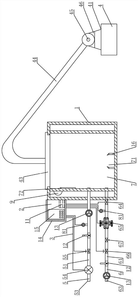
[0031] combine Figure 1-Figure 4 shown;

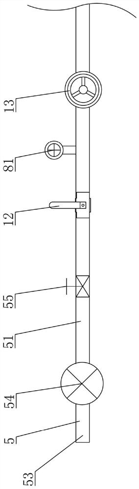
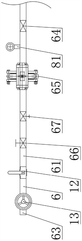
[0032] An automatic control system for a baking oven, comprising a furnace body 1 and an electric control cabinet 2, and a connection circuit 3 is provided between the furnace body 1 and the electric control cabinet 2, the connection circuit 3 includes an end cover lifting power unit 4, a combustion air Supply and control unit 5, gas supply and control unit 6, combustion condition control and real-time monitoring unit 7 and pressure detection unit 8, end cover lifting power unit 4 includes a drive assembly 41 arranged on the furnace body 1 and is used for control and The drive control module 42 that drives the end cover 43 to lift, the drive assembly 41 includes an end cover 43 arranged on the upper end of the furnace body 1, a cr...


PUM


Abstract

The invention discloses a baking oven automatic control system. The baking oven automatic control system comprises an oven body and an electric control cabinet, a connection loop is also arranged between the oven body and the electric control cabinet, and the connection loop comprises an end cover lifting power unit, a combustion air supply and control unit, a fuel gas supply and control unit, a combustion condition control and real-time monitoring unit and a pressure detection unit. The end cover lifting power unit comprises a driving assembly and a driving control module used for controlling and driving an end cover to ascend and descend, a PLC is arranged in the electric control cabinet, and the driving control module, a combustion air monitoring module, a fuel gas supply control module, a baking module, a pressure detection module and a temperature detection module are all integrally arranged in the PLC, and a power module connected with the PLC is arranged in the electric control cabinet. According to the baking oven automatic control system, detection of multiple indexes and data signal feedback are conducted on a baking oven through the PLC, intelligent operation, visual parameter data display and intelligent control of the baking oven are achieved, and the safety and practicability of the baking oven automatic control system are improved.

Description

technical field [0001] The invention belongs to the technical field of baking ovens, and in particular relates to an automatic control system of a baking oven. Background technique [0002] The traditional metallurgical baking furnace has a huge structure and operates as a whole. Once the equipment fails, it is necessary to overhaul the equipment as a whole. The maintenance project is huge, which consumes a lot of labor and time costs. Basically all of them are carried out by manually switching gate valves. This method is time-consuming and laborious, and there are great potential safety hazards. It is impossible to intelligently adjust the flow rate of the combustion-supporting air pipeline and gas pipeline in real time. Furthermore, the traditional metallurgical baking furnace tank cover is heavy, which is not easy to open and is not conducive to ladle lifting. The operation of the equipment is not stable enough during operation, and the failure rate is high. It is not ea...

Claims


Application Information

Patent Timeline
Patent Type & Authority Applications(China)
IPC IPC(8): B22D41/015B22D46/00
CPCB22D41/015B22D46/00
Inventor 刘瑞萍
Owner LUOYANG SHENGXIN INDAL & MINING EQUIP
Why Eureka
Try Eureka