
Traction mechanism for glass substrate production

A technology of glass substrate and traction mechanism, which is applied in the direction of conveyor objects, conveyor control devices, furnaces, etc. It can solve problems such as insufficient static friction, too large or too small clamping force, and material blocking in the furnace to ensure molding High quality, guaranteed warping grade, and easy maintenance

Active Publication Date: 2021-10-26
RAINBOW (HEFEI) LIQUID CRYSTAL GLASS CO LTD
View PDF8 Cites 4 Cited by
  • Summary
  • Abstract
  • Description
  • Claims
  • Application Information

AI Technical Summary

Problems solved by technology

However, in the existing traction mechanism, the clamping force of the traction roller on the glass plate cannot be accurately evaluated or adjusted, and the clamping force is prone to be too large or too small
If the clamping force of the traction roller is too large, it is easy to cause the hardened glass plate to be stressed to form dark cracks. When the glass plate is pulled down by multiple sets of traction rollers or the glass plate is shaken by cross-cutting, the cracks will be further extended and expanded to cause the plate to break. It may even lead to the risk of material blocking in the furnace, causing irreparable losses to key molding equipment and production quality; if the clamping force of the traction roller is too small, the static friction force between the boss of the short roller and the contact surface of the glass plate will be insufficient, which will affect the pulling effect of the short roller And glass substrate warping grade is stable, the improvement of glass substrate molding quality and grade consistency cannot be guaranteed

Method used

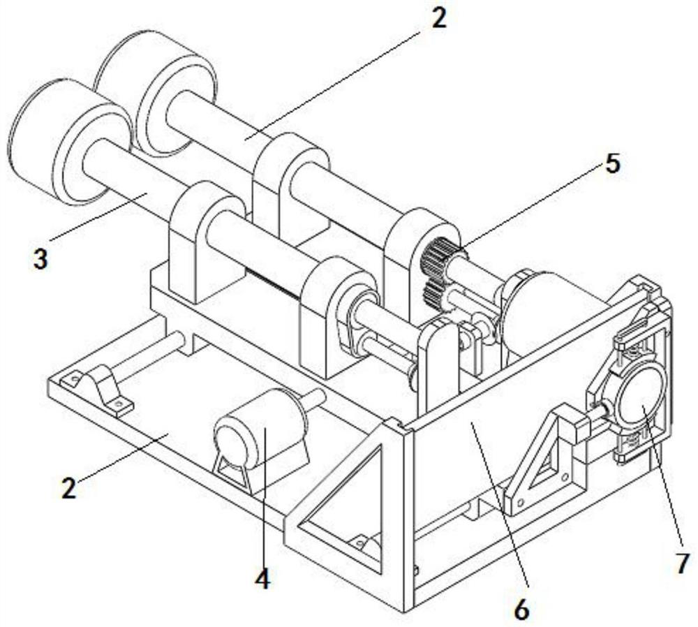
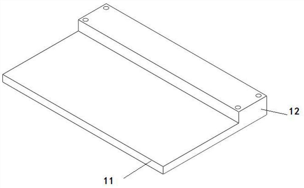
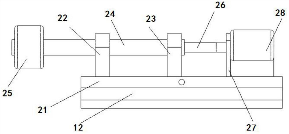

Image

  • Traction mechanism for glass substrate production
  • Traction mechanism for glass substrate production
  • Traction mechanism for glass substrate production

Examples


Embodiment Construction

[0036] The following will clearly and completely describe the technical solutions in the embodiments of the present invention with reference to the accompanying drawings in the embodiments of the present invention. Obviously, the described embodiments are only some, not all, embodiments of the present invention. Based on the embodiments of the present invention, all other embodiments obtained by persons of ordinary skill in the art without creative efforts fall within the protection scope of the present invention.

[0037]In describing the present invention, it is to be understood that the terms "opening", "upper", "lower", "thickness", "top", "middle", "length", "inner", "surrounding" etc. Indicating orientation or positional relationship is only for the convenience of describing the present invention and simplifying the description, and does not indicate or imply that the components or elements referred to must have a specific orientation, be constructed and operated in a spe...


PUM


Abstract

The invention discloses a traction mechanism for glass substrate production. The traction mechanism comprises a mounting base, a floating traction structure and a fixed traction structure are respectively mounted at the front side and the rear side of the upper end of the mounting base, and an adjusting driving mechanism for moving the floating traction structure is further mounted at the front side of the upper end of the mounting base; and the floating traction structure is connected with the fixed traction structure through a transmission mechanism, a heat insulation assembly is installed at the right side of the upper end of the fixed traction structure, and a clamping force display structure is installed at the right side of the heat insulation assembly. According to the traction mechanism, the floating traction structure, the fixed traction structure and the transmission mechanism are jointly matched to perform traction forming on a glass tape, and the clamping force of the floating traction structure and the fixed traction structure on a glass plate can be accurately adjusted through the adjusting driving mechanism and the clamping force display structure, so that the clamping force of the floating traction structure is effectively prevented from being too large or too small, the stability of the production state and the warping grade of a glass substrate can be ensured, and the forming quality of the glass substrate is ensured.

Description

technical field [0001] The invention belongs to the field of glass substrate production equipment, in particular to a traction mechanism for glass substrate production. Background technique [0002] The overflow pull-down is to send the molten glass into the overflow brick made of zircon refractory material with an inclined groove inside. The wall surface finally converges at the tip of the overflow brick to form a glass ribbon. Under the action of the gravity of the glass itself and the edge pulling machine and traction mechanism, it overcomes the influence of surface tension. According to the temperature system of the molding process, after shaping, annealing and cutting Form the substrate vitreous plate. During the forming process by this method, the glass surface does not contact any material, and has the characteristics of a free surface with flame polishing effect and extremely high flatness of the plate surface. However, in the existing traction mechanism, the clamp...

Claims


Application Information

Patent Timeline
Patent Type & Authority Applications(China)
IPC IPC(8): B65G49/06B65G43/00
CPCB65G49/061B65G43/00
Inventor 何志锋程肇琦陆兵兵赵荣
Owner RAINBOW (HEFEI) LIQUID CRYSTAL GLASS CO LTD
Learn More