Polishing device for building engineering machine part maintenance

A technology of mechanical parts and construction engineering, applied in the direction of grinding drive device, grinding/polishing safety device, grinding workpiece support, etc., can solve the problems of environmental damage, low efficiency, palm scratches, punctures, etc., and achieve improvement Polished quality effect

Active Publication Date: 2021-10-29
江苏淮海新材料科技有限公司
View PDF7 Cites 1 Cited by
  • Summary
  • Abstract
  • Description
  • Claims
  • Application Information

AI Technical Summary

Problems solved by technology

[0003] At present, the round steel pipe fittings are generally polished with hand-held electric tools during maintenance and grinding. This grinding method is inefficient, poor in safety, and the quality of the polished surface is poor. The surface of the round steel pipe fittings, so the surface of the round steel pipe fittings needs to be cleaned after grinding, otherwise it will cause scratches and punctures to the palms of the workers in the later process; in addition, because there are many round steel pipe fittings before grinding Put it randomly, so there will be dirt and dust on the surface. Therefore, during the grinding process, the metal powder that falls off will be mixed with ordinary dirt and other dust, which is not conducive to the later recycling of metal powder. If it is not handled properly, It will also cause corresponding damage to the environment

Method used


Image

  • Polishing device for building engineering machine part maintenance
  • Polishing device for building engineering machine part maintenance
  • Polishing device for building engineering machine part maintenance

Examples


Embodiment Construction

[0030] In order to make the technical means, creative features, goals and effects achieved by the present invention easy to understand, the present invention will be further described below in conjunction with specific embodiments.

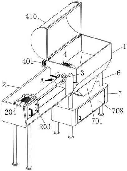
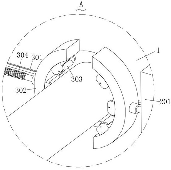
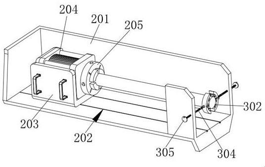
[0031] Such as Figure 1-Figure 9 As shown, a grinding device for maintenance of construction machinery parts according to the present invention includes a box body 1, a pushing structure 2 is installed at one end of the box body 1, and a correction structure 3 is installed at one end of the box body 1, A polishing structure 4 is installed inside the box body 1, a height adjustment structure 5 is installed on one side of the box body 1, a support column 6 is fixedly connected to the bottom end of the box body 1, and the bottom of the box body 1 A dust collection structure 7 is installed at the end, and the grinding structure 4 includes a rotating shaft 402. The inner rotation of the box 1 is equipped with a rotating shaft 402, and the surface of the...


PUM


Abstract

The invention relates to the technical field of polishing devices, in particular to a polishing device for building engineering machinery part maintenance, which comprises a box body, a pushing structure is mounted at one end of the box body, a correcting structure is mounted at one end of the box body, a polishing structure is mounted in the box body, and a height adjusting structure is mounted on one side of the box body; supporting columns are fixedly connected to the bottom end of the box body, a powdered scrap collecting structure is installed at the bottom end of the box body, and the polishing structure comprises a rotating shaft; the surface of a polished round steel pipe fitting can be cleaned through brushes, and meanwhile, the polishing height of a grinding wheel can be adjusted through the height adjusting structure; the phenomenon of eccentric swinging of the other end of the round steel pipe fitting in the rotating process can be prevented through the correcting structure, so that the polishing quality of the round steel pipe fitting is improved; and metal substances in the dust can be separated from common dust through magnetic suction plates.

Description

technical field [0001] The invention relates to the technical field of grinding devices, in particular to a grinding device for maintenance of construction machinery parts. Background technique [0002] In the construction process of construction projects, in order to reduce the labor intensity of workers, various mechanical equipment are generally used. However, during the long-term use of mechanical equipment, some round pipe supports or connecting parts will be corroded and worn. At this time, it is necessary to re-grind, refinish and paint the round pipe fittings. [0003] At present, the round steel pipe fittings are generally polished with hand-held electric tools during maintenance and grinding. This grinding method is inefficient, poor in safety, and the quality of the polished surface is poor. The surface of the round steel pipe fittings, so the surface of the round steel pipe fittings needs to be cleaned after grinding, otherwise it will cause scratches and punctu...

Claims


Application Information

Patent Timeline
IPC IPC(8): B24B27/033B24B55/06B24B41/06B24B47/12B24B55/00
CPCB24B27/033B24B55/06B24B41/067B24B47/12B24B55/00
Inventor 胡加林吴洪厂李良成
Owner 江苏淮海新材料科技有限公司
Why Eureka
Try Eureka