[0036] Next, the technical solutions in the embodiments of the present invention will be described in connection with the drawings of the embodiments of the present invention, and it is understood that the described embodiments are merely the embodiments of the present invention, not all of the embodiments. Based on the embodiments of the present invention, all other embodiments obtained by those of ordinary skill in the art are in the range of the present invention without making creative labor premise.
[0037] In order to make the above objects, features, and advantages of the present invention, the present invention will be further described in detail below with reference to the accompanying drawings and specific embodiments.
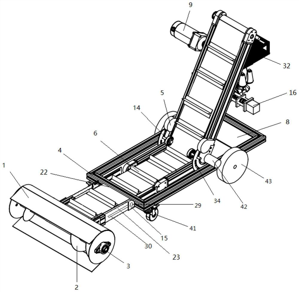
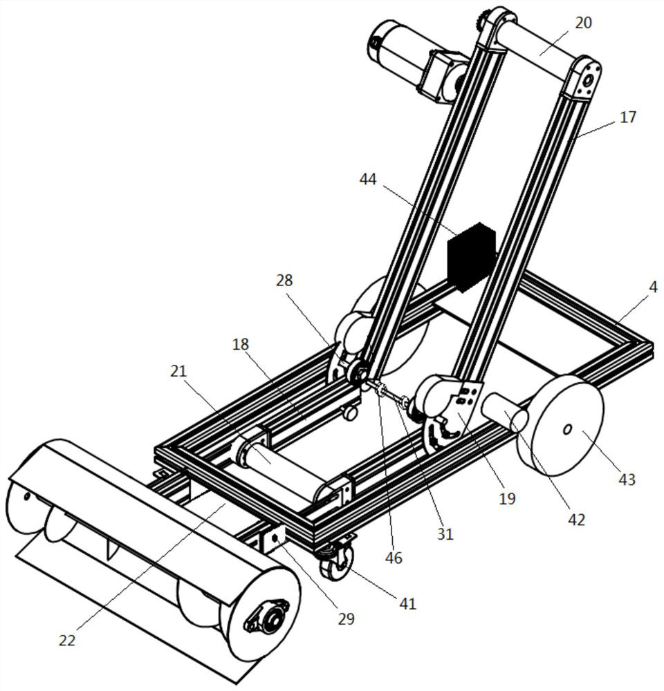
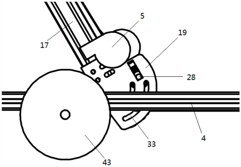
[0038] Refer Figure 1-8 The present invention provides a multi-function integrated intelligent grain machine, including a rack, conveyor belt 7, a collection mechanism, a screening mechanism
[0039]The rack includes a base frame 4; two beams 18 are fixedly mounted on the bottom frame 4; the two beams 18 are horizontally and symmetrically disposed; the two beam 18 is fixedly mounted; the telescopic mechanism extends The bottom frame 4 is fixed to the collecting mechanism; the two beams 18 rotate through the two rotation modulating plates 19, respectively, and the two rotation adjustment plates 19 are defined in the two-horned beam 18 and the bottom frame 4 two opposite side walls. There is a position between the beam 18; the horizontal fixation shaft 31 is fixed between the two rotating adjustment plates 19; the screening mechanism is fixedly mounted on one side of the rotating beam 17 away from the collection mechanism; the two rotary beams 17 are remotely adjusted One end of the board 19 is mounted by the bearing; the two beams 18 are mounted between the two beams 18; the conveyor belt 7 is wound around the active shaft 20, the connecting shaft 31, the drive shaft 21 and the shaft in the collection mechanism. 24 Transmission; the active shaft 20 is driven by the first motor 9 fixed to the rotating beam 17.
[0040] The sidewall of the beam 18 is perpendicular to the beam 18 in the base frame 4; the beam 18 is extended from one end of the side wall of the bottom frame 4 to the middle of the bottom frame 4; the rotary beam 17 is fixed to the rotary adjustment plate 19; rotation adjustment plate 19 and the beam 18 Through the bolt, the rotation adjustment plate 19 can rotate relative to the beam 18, so that the angle can be changed; the connecting shaft 31 is rotated with a plurality of rollers 46 by the bearing; which can better carry the conveyor belt 7 to operate More stable; the bottom frame 4 is opened up close to one side of the collecting device with a groove 22, and the conveyor belt 7 penetrates the groove 22; the groove 22 can provide the conveying belt 7 to provide a working space to transport the belt 7 normal transport.
[0041] Further optimization scheme, the rotating adjustment plate 19 is opened with a center of the first arc groove 33 and the second arc groove 39; the first arc groove 33 and the central arc-shaped groove 39 are connected to the connection. The axis of the shaft 31 is coincident; a threaded hole 34 is opened to the side wall of the beam 18 and the first arc groove 33 and the second arc groove 39, respectively, and the rotational adjustment plate 19 and the The rotary beam 17 is fixed.
[0042] When the positional relationship between the fixed beam 18 and the rotating adjustment plate 19, the first arc groove 33 and the second arc groove 39 are respectively used, respectively, and extends into the side wall of the beam 18 and the first curved shape, respectively. Within the two threaded holes 34 corresponding to the slot 33 and the second arc slot 39, the two bolts are threaded with the two threaded holes 34, and the position between the rotational adjustment plate 19 and the beam 18 can be fixed after tightening.
[0043] Further optimization scheme, the rotation adjustment board 19 is further fixed to the support shaft 28; one end of the support shaft 28 extends above the conveyor belt 7 and the tension wheel 14 is mounted by the bearing; the peripheral wall of the tension wheel 14 and the conveyor belt 7 Face.
[0044] A thread is opened on the support shaft 28, and is mounted on the rotation adjustment plate 19 by a nut, and the rotation adjustment plate 19 is opened to the position corresponding to the support shaft 28; the nut on which the support shaft 28 can be made after The support shaft 28 slides the adjustment position within the direct slide groove 40 to accommodate the rotary beam 17 of different angles, so that the conveying belt 7 can effectively achieve bending.
[0045] Further optimization scheme, the telescopic mechanism includes two rail 15; the two rails 15 are fixed to the opposite side of the two beams 18, respectively, and horizontally symmetrically disposed; the rail 15 is close to one end of the bottom frame 4 and extended to the bottom frame 4 External; sliding in the slide rail 15 is provided with a slide 23; one end of the slide plate 23 is defined within the rail 15, and the other end of the slide 23 is fixed to the collecting device; the slider 23 opens with a pass groove 30; the slide rail 15 is horizontally There is a bolt hole 29; the bolt hole 29 corresponds to the passage 30 position.
[0046] The skateboard 23 can slide in the rail 15, so that the distance of the collecting device to the bottom frame 4 can be adjusted, after adjusting, the bolt is passed through the bolt hole 29 and the pass groove 30, and tighten with the nut, so that the slide 23 can be used in the slide 23 The position in 15 is locked, so that the conveyor tape 7 is relaxed when used for a long time, and the distance to the collecting device to the bottom frame 4 can increase the conveying belt 7, and then the slide plate 23 and the nut can be used. The position of the slide rail 15 is fixed, and the life of the conveyor belt 7 can be used normally; the surface of the conveyor belt 7 is extended, and a plurality of baffles 6 are fixed vertically, and the baffle 6 is defined in two tension wheel 14. The distance between the length is less than between the two tension wheel 14, ensuring that the tension wheel 14 and the baffle 6 do not interfere with each other; the tension wheel 14 can keep the conveying belt 7 from the rotating shaft 24 to the tensioner 14 portion, from The tensioner 14 to the active shaft 20 can follow the rotary beam 17 upward, the angle of the rotary beam 17 is bent is 30 ° to 150 °; the baffle 6 can be more convenient to transport food to the height.
[0047] Further optimization scheme, the collecting mechanism also includes a cylinder 1; the collector 1 is opened to the side of the bottom frame 4, and the collector 1 is opened from the end of the bottom frame 4, and the two skate plates 23 are detachable, respectively. Connecting on both sides of the grain port; both ends of the shaft 24 penetrate the columnar tube 1 and rotate the diamond bearing 3 and the collector 1 to the collector 1 on the end surface of the collector 1; weld 2 .
[0048] The collected cartridge 1 passes on one side away from the bottom frame 4, and the grain port is opened from the side of the bottom frame 4, and the conveyor belt 7 passes through the grain port and the rotary shaft 24 transmission; the twinkle 2 of the rotary axis 2 Instead, the food can be transported to the middle of the conveyor belt 7 at the same time.
[0049] Further optimization scheme, the screening mechanism includes a receiving frame 32; the receiving frame 32 is a square frame structure and the top surface tilt setting; the side of the receiving frame 32 is fixedly mounted on the rotary beam 17 by the link 25; the bottom surface of the receiving frame 32 is fixedly mounted There is a filter 10; the top surface of the receiving frame 32 is elastically coupled to the screen 11 by a plurality of spring 12; the screen 11 is defined directly below the active shaft 20; the top surface side of the receiving frame 32 is fixedly installed with a second motor 13; The output of the second motor 13 is fixedly connected to the rotary 26; the axis of the end surface of the wheel 26 is axially coupled to the drive rod 27 and the edge of the screen 11.
[0050] The link 25 is hinged to the rotary beam 17, and the hinge position is mounted with a fastening knob 45, and the fastening knob 45 can rotate the receiving frame 32, thereby adapted to the rotating beam 17 of different angles, and after the receiving frame 32 adjusts the angle, tighten The sticker 45 can realize the positional lock of the receiving frame 32; the second motor 13 can be shaken by the screen 11, so that the food falling filter 10 can be screened to carry out secondary bughing, improve the proprietary efficiency; The network is smaller than the screen 11, and the size of the mesh of the filter 10 is just through the granule.
[0051] Further optimization scheme, the base frame 4 top surface is fixed to the position of the filter 10 fixedly mounted, the weighing device 8; the weighing device 8 can be placed on the grain bag, and the food in the grain bag is weighed, and the standardized food package is realized. .
[0052] Further optimization solution, the bottom surface of the receiving frame 32 is fixedly mounted having a sealing mechanism, and the sealing mechanism includes two mounting plates 35 fixed to the receiving frame 32 and a stitching machine disposed between the two mounting plates 35; two mounting plates The parallel fixation of 35 is fixedly installed with several guide shafts 37; the guide shaft 37 is slidably connected to the stitching machine 36; the two mounting plates 35 are also rotated between the two mounting plates 35, and the screw 38 is mounted; the screw 38 is parallel to the guide shaft; screw 38 Threading the sewing machine 36 and the stitching machine 36 threaded; one end of the screw 38 penetrates the mounting plate 35 and transmits a third motor 16.
[0053] The third motor 16 can be rotated by the screw 38, so that the stitching machine 36 can be moved on the guide shaft 37, so that the opening of the food bag is fully sealed; the third motor 16 is electrically connected to the control unit 44.
[0054] Further optimization scheme, the first motor 9, the second motor 13, the third motor 16, and the weighing device 8 are electrically connected to the control unit 44 fixed to the bottom frame 4.
[0055] The weighing device 8 is a resistance strainable chip sensor. As the weight increases, the larger the strain, thereby achieving the weight of the measurement, weighing device 8, the first motor 9, the second motor 13, the third motor 16, and stitches 36 are controlled by the control unit 44, which can be controlled, which can be automated, gains, and intrinsic, sealing.
[0056] Further optimization solution, the bottom frame 4 is fixed to the position of the rotation adjustment plate 19 fixed to the fan 5; the fan 5 is toward the conveyor belt 7.
[0057] The fan 5 can initially purge dust on the food on the conveyor belt 7, the wind blows blown out of the fan 5 can blow away the light impurities, but it is not enough to blow the food, the heterogenesis needs to pass the screen 11 in the screening device. The filter 10 is buurous.
[0058] The bottom frame 4 is fixed to the side of the collector 1 fixedly mounted a plurality of universal wheel 41; the bottom frame 4 is fixed to the side of the weighing device 8 fixedly mounted a number of travel wheel 43, the travel wheel 43 is attached to the bottom The fourth motor 42 on the top surface of the frame 4 is driven, and the fourth motor 42 is electrically connected to the control unit 44.
[0059] When the present invention is used, the bolts in the two threaded holes 34 are first loops, rotate the rotary beam 17 to the appropriate position to accommodate the size of the food bag, and then tighten the bolt to fix the rotary beam 17 position, then loosen tight The fixing link 45, the rotating link 25 causes the receiving frame 32 horizontally, tighted the fixed knob 45; manually put one end of the opening of the food bag into the stitching machine 36, activates the first motor 9, the second motor 13, the fourth motor 42 and The fan 5, the fourth motor 42 drives the entire gain machine, and the first motor 9 drives the active shaft 20, the active shaft 20 is rotated by the conveyor belt 7, and the shaft 24 is rotated, and the scorpion 2 will be grounded. The food is collected and delivered to the conveyor belt 7, and the food is moved under the conveyor belt 7. When the fan 5 is passed, the fan 5 blows the light impurities on the food surface, and then the food from the conveyor belt 7 is up to the screen 11 On the upper, the second motor 13 rotates the rotation wheel 26, and the wheel 26 drives the drive rod 27 to reciprocate, the transmission rod 2 roses the screen 11 to sway, so that the food on the screen 11 can be filtered to mix, the impurities of large particles are Interception on the screen 11, the food is filled with the screen 11, and the filter 10 is slightly vibrated under the vibration generated by the second motor 13, which makes the food secondary filtration, smaller The particles are intercepted on the filter 10, and the grain of the filter 10 falls into the grain bag placed on the weighing device 8, when the weight reaches the specified value, the first motor 9, the second motor 13, the fourth motor 42 and the fan 5 stops, the third motor 16 is started, the screw 38 is rotated, so that the sewing machine 36 is axially moved, and the sewing machine 36 works the sealing of the food bag. After the sealing is completed, the third motor 16 stops working, replacing new After the food bag, the same operation can be repeated to automate it again.
[0060] In the description of the invention, it is to be understood that the term "longitudinal", "horizontal", "upper", "lower", "front", "post", "left", "right", "vertical", The orientation relationship between "horizontal", "top", "bottom", "inside", "outside", etc. is based on the orientation or positional relationship shown in the drawings, but is only for convenience of description, not indication or I suggest that the device or element must have a specific orientation, constructed and operated in a particular orientation, and thus is not to be construed as limiting the invention.
[0061] The embodiments described above are merely described in the preferred embodiment of the present invention, and are not limited to the scope of the invention, and those of ordinary skill in the art will make various technical solutions according to the present invention without departing from the spirit of the invention. Deformation and improvement, should fall within the scope of protection determined according to the claims of the present invention.