
Annealing furnace and annealing process for martensitic stainless steel 2Cr13 wire rods

A martensitic stainless steel, 2cr13 technology, applied in the direction of process efficiency improvement, furnace, manufacturing tools, etc., can solve the problems of incomplete heat recovery, high heat loss, large waste of resources, etc., to avoid excessive heat loss, The effect of increasing the heating rate and improving the heating efficiency

Pending Publication Date: 2021-10-29
刘自强
View PDF10 Cites 0 Cited by
  • Summary
  • Abstract
  • Description
  • Claims
  • Application Information

AI Technical Summary

Problems solved by technology

[0004] In order to make up for the deficiencies of the existing technology, the height of the furnace door opening when the wire rod enters the furnace door is fixed during annealing, so that the heat lost is high, the heat loss is large, and the use of nitrogen to absorb heat requires a lot of nitrogen, heat recovery is not complete, and resources are wasted. problem, the present invention proposes a kind of annealing furnace and annealing process of martensitic stainless steel 2Cr13 wire

Method used


Image

  • Annealing furnace and annealing process for martensitic stainless steel 2Cr13 wire rods
  • Annealing furnace and annealing process for martensitic stainless steel 2Cr13 wire rods
  • Annealing furnace and annealing process for martensitic stainless steel 2Cr13 wire rods

Examples


Embodiment approach

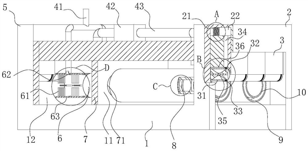
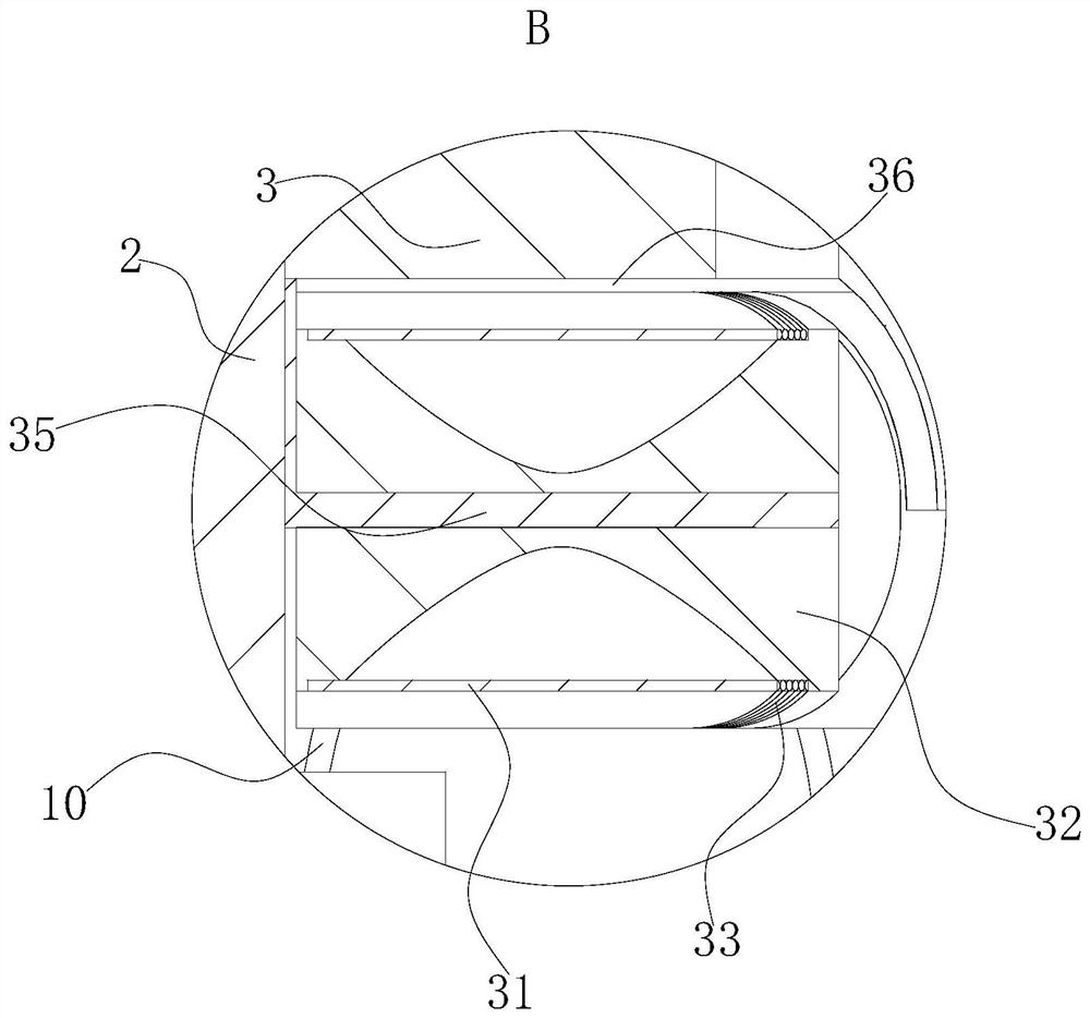
[0039] As an embodiment of the present invention, the lower end of the furnace door baffle plate 3 is provided with a groove 2 36 along the width direction, and a rotating shaft 35 is fixedly installed in the groove 2 36, and a rolling shaft 35 is rotatably installed on the rotating shaft 35. Column 32.

[0040] During work, upwardly open the furnace door baffle 3 in the inner groove 22 of the front furnace door 2, put in the wire rod that needs to be annealed, and then close the furnace door baffle 3 downwards, which is now located at the lower end of the furnace door baffle 3 The roller 32 in the second groove 36 is in direct contact with the wire to be annealed. After the roller 32 is in direct contact with the wire, the roller 32 rotates on the rotating shaft 35, preventing the furnace door baffle 3 from closing downwards. When directly contacting with the wire rod, the surface of the wire rod will be scratched. At the same time, the rotation of the roller 32 can also make...


PUM


Abstract

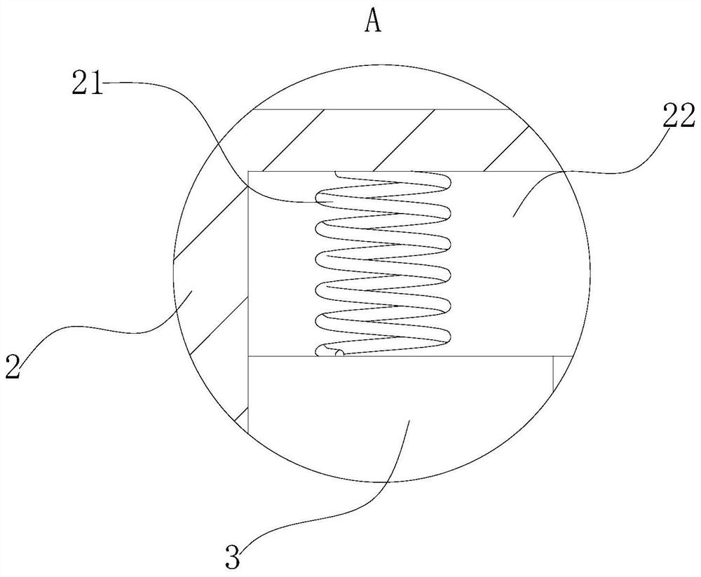
The invention belongs to the technical field of annealing equipment, and particularly relates to an annealing furnace and an annealing process for martensitic stainless steel 2Cr13 wire rods. The annealing furnace comprises a box body; a front furnace door and a rear furnace door are fixedly installed at the two ends of the box body respectively; a partition plate is fixedly installed in the box body; a material hole is formed in the partition plate; the partition plate divides the interior of the box body into an annealing chamber and a cooling chamber which are hollow; an air inlet pipeline and a circulating pipeline are fixedly installed on the upper surface of the box body; an exhaust pump is fixedly installed on the circulating pipeline; a plurality of infrared heating rings are installed in the annealing chamber; a first groove is formed in the front furnace door; a first spring is fixedly installed in the first groove; and the lower end of the first spring is fixedly connected with a furnace door baffle. According to the annealing furnace and the annealing process, through the arrangement of the furnace door baffle, gaps formed between the furnace doors and the interior of the box body as well as the rod wires can be reduced; heat loss is reduced; and meanwhile, nitrogen can be recycled, so that the production cost is reduced.

Description

technical field [0001] The invention belongs to the technical field of annealing equipment, in particular to an annealing furnace and an annealing process for a martensitic stainless steel 2Cr13 wire rod. Background technique [0002] Heat treatment furnaces are divided into annealing furnaces, quenching furnaces, tempering furnaces, normalizing furnaces, and quenching and tempering furnaces. They are mainly used for annealing of large carbon steel and alloy steel parts; tempering of surface quenched parts; heat treatment processes such as stress relief annealing and aging of weldments. Heating methods include electric heating, oil, gas, coal, and hot air circulation. Annealing furnace is a new type of heat exchange equipment. The annealing furnace is an energy-saving periodic operation furnace with a super energy-saving structure and a fiber structure, saving 60% of electricity. [0003] There are also some technical solutions about annealing furnaces in the prior art. Fo...

Claims


Application Information

Patent Timeline
IPC IPC(8): C21D9/54C21D1/26C21D1/42B08B1/02
CPCC21D9/54C21D9/0062C21D1/26C21D1/42C21D9/0006C21D9/0018B08B1/50B08B1/20B08B1/12Y02P10/25Y02P10/20
Inventor 刘自强夏子涵
Owner 刘自强
Learn More