Design method of variable curvature optical integrator

A technology of an optical integrator and a design method, applied in the field of variable curvature optical integrator, can solve the problems of inconvenient installation and adjustment, high light energy loss rate, poor irradiation uniformity at the edge of the spot, etc., and achieves the improvement of performance and irradiation energy. Effect

Pending Publication Date: 2021-10-29
CHANGCHUN UNIV OF SCI & TECH
5 Cites 0 Cited by

AI-Extracted Technical Summary

Problems solved by technology

[0003] At present, the compact optical integrator improves the uniformity of the beam by increasing the length of the beam passing path, but the structure is too large and the installation is inconvenient; the cluster optical integrator ensures the consistency of the optical axis and effectively avoids the side lobe effect, but cannot Compensation of edge light, poor uniformity of irradiation at the edge of the spot, exit-pupil optical integrator, prevents superimposed imaging blur, but more affects the uniformity of edge irradiation; symmetrical optical integrator uses edge lens, expands the aperture of the integrator, and separates the projection lens group The method of compensating the uniformity of the edge of the irradiated surf...

Method used

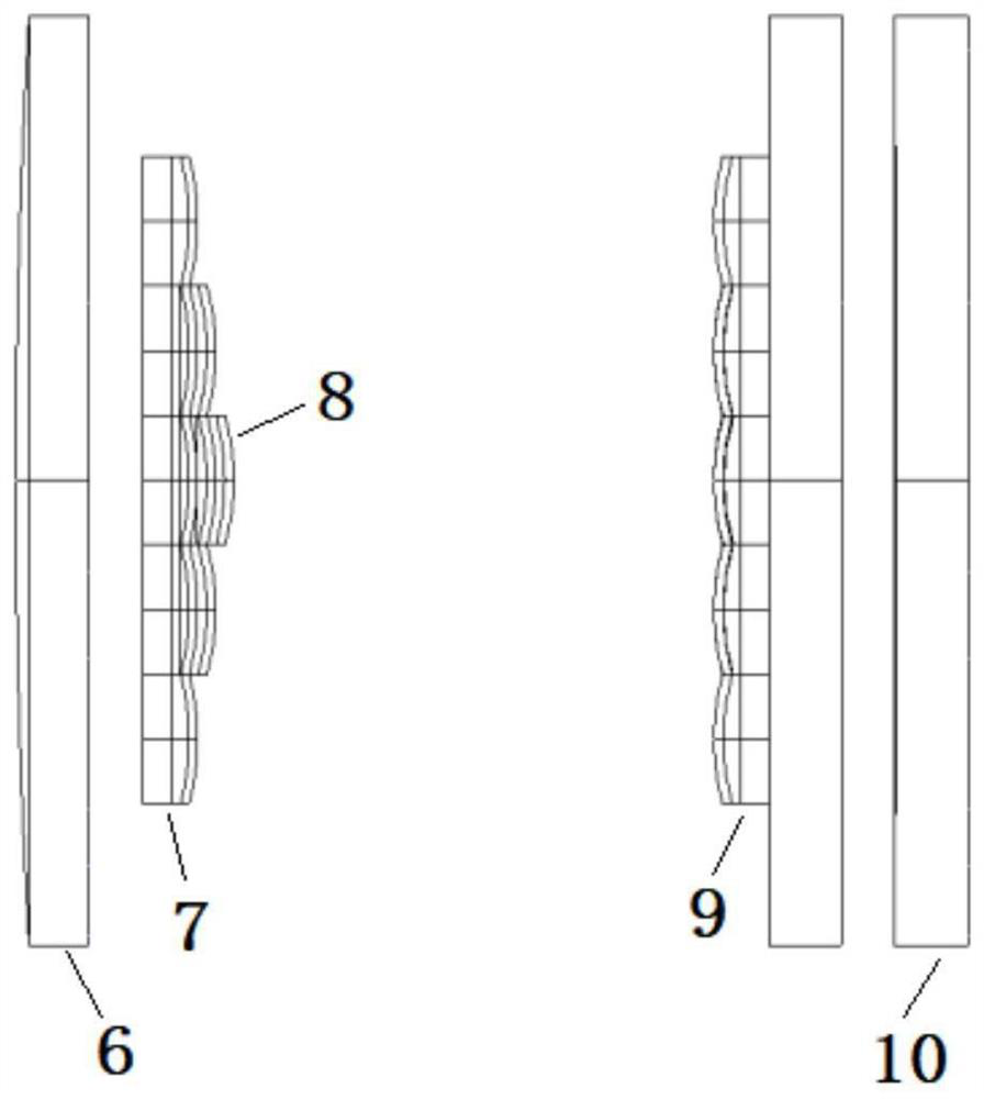
Illustrate present embodiment in conjunction with Fig. 2, Fig. 2 is a kind of solar simulator variable curvature optical integrator structural diagram with the function of improving output light spot edge energy that adopts the method design of present embodiment, after variable curvature optical inte...

Abstract

The invention discloses a design method of a variable curvature optical integrator, relates to the technical field of optical instrument design, and the design method can improve the edge energy of output light spots and improve irradiation uniformity while ensuring that the irradiance reaches a solar constant. The design method comprises the following steps: determining the aperture and the number of integrator channels according to a Fresnel number; establishing a mathematical model of a two-dimensional plane of the variable curvature optical integrator by using a Fresnel diffraction formula, deducing a light intensity distribution mathematical function on a working surface, and determining the focal length of each circle of sub-eye lens; wherein the rear surface of the integrator field lens group adopts aspheric design, so that the side lobe effect is eliminated, and the imaging quality is improved. The variable curvature optical integrator is convenient to install, and improves the edge energy of output light spots and the irradiation uniformity under the condition that the irradiance reaches the solar constant.

Application Domain

Optical elements

Technology Topic

Fresnel numberOptical instrument +12

Image

  • Design method of variable curvature optical integrator
  • Design method of variable curvature optical integrator
  • Design method of variable curvature optical integrator

Examples

  • Experimental program(1)

Example Embodiment

[0023] In order to make the purposes, technical solutions and advantages of the embodiments of the present invention clearer, the technical solutions in the embodiments of the present invention will be clearly and completely described below with reference to the accompanying drawings in the embodiments of the present invention. Obviously, the described embodiments These are some embodiments of the present invention, but not all embodiments. Based on the embodiments of the present invention, all other embodiments obtained by those of ordinary skill in the art without creative efforts shall fall within the protection scope of the present invention.
[0024] This embodiment provides a method for designing a variable curvature optical integrator, including the following specific steps:
[0025] S1. Each small lens of the variable-curvature optical integrator 1 is designed as a square prism lens, the field lens group 7 is 25 small lenses of different thicknesses, the projection lens group 9 is 25 small lenses of equal thickness, and the eye lenses of each circle are in the center Symmetrical arrangement, the same circle eye lens has the same focal length and equal thickness, different circle eye lenses have different focal lengths and different thicknesses, see the structure diagram of the integrator figure 2;
[0026] S2. Determine the installation position of the variable curvature optical integrator 1. The entrance pupil of the variable curvature optical integrator 1 is placed at the second focal plane of the ellipsoid condenser lens 2, and the exit pupil of the variable curvature optical integrator 1 is placed on the object of the collimating lens 4. 1mm in front of the square focal plane, see figure 1;Use the Fresnel number to evaluate the diffraction effect, design an integrator 1 with a Fresnel number greater than 500, and determine the aperture and number of channels according to the uniformity of irradiation and energy utilization;
[0027] The Fresnel number is defined as:
[0028]
[0029] In the formula, OPD is the optical path difference, r is the radius of the aperture of the sub-eye lens, λ is the wavelength of the incident light, and L is the working distance.
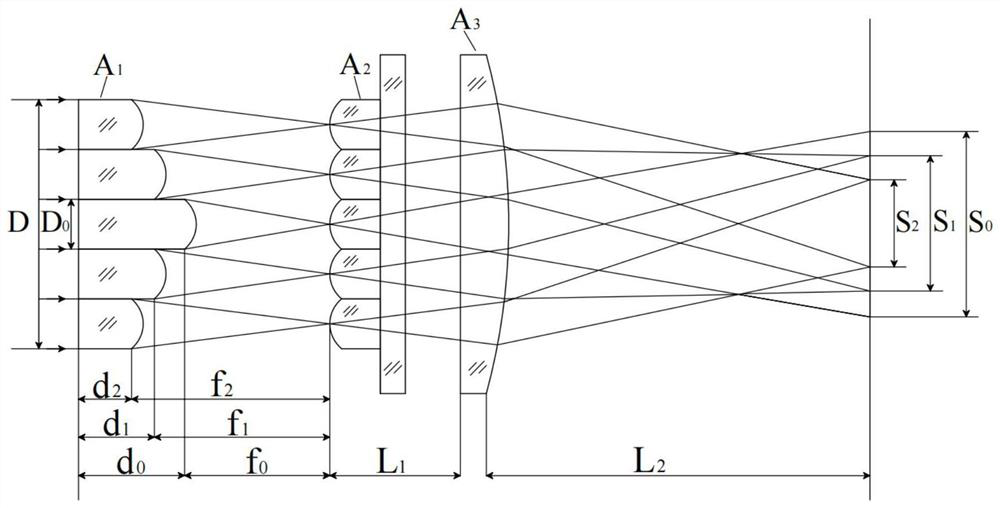
[0030] Taking the central sub-eye lens 8 as an example, assuming that parallel light waves are incident, the focal length of the focusing lens is f F , the irradiation area is S 0 , the aperture of the integrator 1 is D, and the aperture of the sub-eye lens is D 0 , the number of radial channels is m, the Substituting into the above formula, the calculation formula of the relationship between the integrator 1 and the Fresnel number is as follows:
[0031]
[0032] Let F N greater than 500, f F and S 0 Unchanged, take D=35.5mm, S 0 = 200mm, f F =800mm, λ=770nm, substitute into the above formula to get D 03.12mm, because m=D/D 0 , that is, m<11.378. Let ν be the energy utilization rate, the integrator energy utilization rate formula is:
[0033]
[0034] Establish 5 lens array models of 3×3, 4×4, 5×5, 6×6, 7×7, etc. According to the above formula, the relationship between the number of channels and the energy utilization rate can be obtained, see Figure 4. Then simulate and compare the relationship between the number of channels and the inhomogeneity under the irradiation area of ​​Φ200, see Figure 5. In summary, the value m=5 is the best value. Then the number of integrator 1 channels is 25, D 0 =7.1mm (field lens group is the same as projection lens group), F N The minimum value is 576.3, and the design parameters are shown in Table 1.
[0035] Table 1
[0036] Integrator 1 name Variable Curvature Optical Integrator Lens diameter/(mm) 7.1 Number of radial channels 5 number of channels 25 Irradiation area/(mm) 200 Minimum Fresnel number 576.3
[0037] S3. Establish a mathematical model of each circle eye lens of the integrator 1 on a two-dimensional plane, deduce the mathematical function of the light intensity distribution on the working surface of the integrator, and divide the rectangular ring according to each circle eye lens, that is, the energy of each circle eye lens can be obtained, and the The complex amplitude distribution of the initial light wave; according to the effective irradiation area and the edge area, the irradiation area of ​​other circle eye lenses is obtained, and finally the focal length of the integrator 1 is determined;
[0038] First, the eye lenses of each circle of integrator 1 are divided into several rectangular rings, see Image 6 , the coordinate system xoy, r is established in the plane area of ​​the lens array m,n Number each lens, M and N are the number of lenses along the x and y axes. Taking the central sub-eye lens 8 as an example, the function R of the central sub-eye lens 8 1 (x a ,y a ) formula is:
[0039] R 1 (x a ,y a )=r 3,3 +…+r M-2,N-2
[0040] Complex-amplitude transmittance function t of the center sub-eye lens 8 1 (x,y) formula is:
[0041]
[0042] In the formula: δ(x a -mD 0 ,y a -nD 0 ) is the impulse function, is the aperture function.
[0043] The Fresnel diffraction formula is:
[0044]
[0045] In the formula: i is the imaginary unit, k is the wave number of the light wave, z is the length of the wave transmission path, x, y are the starting coordinates, x 1 , y 1is the end point coordinates.
[0046] Ideally, assume that the complex amplitude distribution of a plane wave with wavelength λ is E 0 (x,y), the light wave is incident on the field lens group A of the optical integrator 1 After that, the broad light wave is filtered by the field lens group A 1 Divided into thin light waves, converged and incident on projection lens group A 2 Integral imaging, the transmission distance is f 0 , the light wave is re-incident to the focusing lens A 2 Imaging, the transmission distance is L 1 , and finally a complex amplitude image is formed on the working surface, and the transmission distance is L 2 , see image 3 , the complex amplitude distribution of the light wave is obtained as:
[0047]
[0048] then S 0 The mathematical function of the light intensity distribution on is:
[0049]
[0050] In the same way, the mathematical models of the other two circles of eye lenses are established, and the mathematical function of the light intensity distribution on the working surface is deduced. It is known that the xenon lamp in the optical system has a rated power of 5000W. The spot area of ​​the xenon lamp light source 3 at the second focal plane of the ellipsoid condenser 2 is 35mm. According to each circle of eye lenses, a rectangular ring is divided, and the energy of the central sub-eye lens is 1579.5W. The energy of the two-circle eye lens is 1060.5W, and the energy of the outermost circle eye lens is 610W, that is, the complex amplitude distribution of the initial light wave of each circle eye lens can be known, and it is known that S 2 =200mm, ΔS 2 =3.55mm, according to S 1 =S 2 +2ΔS 2 , S 0 =S 2 +4ΔS 2 , then it can be seen that S 1 =207.1mm, S 0 =214.2mm, the above formulas are programmed by Matlab software, and substituted into the above data to calculate, and the focal length results (the field lens group and the lens lens group are the same) are shown in Table 2.
[0051] Table 2
[0052] lens name central sub-eye lens second circle eye lens outermost circle eye lens Focal length value/(mm) 26.4mm 27.4mm 28.4mm
[0053] S4. In the Zemax software, set the rear surface of each circle eye lens of the field lens group to an even-order aspheric surface, and optimize the quadratic conic coefficient of the even-order aspheric surface to eliminate the imaging stray light (spherical aberration) in the optical system, The optimization result of the integrator is obtained, and the design of the integrator is completed.
[0054] Taking the central sub-eye lens as an example, firstly, input the initial parameters in Zemax software, set multiple field angles, select the material as JGS3, and the structural parameters of the input lens are shown in Table 3.
[0055] table 3
[0056]
[0057] The rear surface of the lens is set to be an even-order aspheric surface for optimization, and the optimization variable is the quadratic conic coefficient. See the optical path diagrams and spot diagrams before and after optimization. Figure 7 and Figure 8 , and the optimization results are shown in Table 4.
[0058] Table 4
[0059] lens name central sub-eye lens second circle eye lens outermost circle eye lens Number of lenses 1 8 16 Diameter/(mm) 7.1 7.1 7.1 Curvature/(mm) 12.10 12.56 13.02 Thickness/(mm) 5 4 3 Quadratic Conic Coefficient -2.231 -2.335 -2.430
[0060] combine figure 2 Describe this embodiment, figure 2 The structure diagram of a solar simulator variable curvature optical integrator with the function of improving the output spot edge energy designed by the method of this embodiment, the rear surface of the variable curvature optical integrator lens adopts an aspherical design, which effectively eliminates the side lobe effect and improves the performance of the optical integrator. The imaging quality and the overall uniformity of the irradiation surface are significantly improved, which has certain reference significance for improving the performance of the solar simulator.
[0061] Finally, it should be noted that: the above embodiments are only used to illustrate the technical solutions of the present invention, but not to limit them; although the present invention has been described in detail with reference to the foregoing embodiments, those of ordinary skill in the art should understand: it can still be Modifications are made to the technical solutions described in the foregoing embodiments, or some technical features thereof are equivalently replaced; and these modifications or replacements do not make the essence of the corresponding technical solutions depart from the spirit and scope of the technical solutions of the embodiments of the present invention.

PUM

no PUM

Description & Claims & Application Information

We can also present the details of the Description, Claims and Application information to help users get a comprehensive understanding of the technical details of the patent, such as background art, summary of invention, brief description of drawings, description of embodiments, and other original content. On the other hand, users can also determine the specific scope of protection of the technology through the list of claims; as well as understand the changes in the life cycle of the technology with the presentation of the patent timeline. Login to view more.

Similar technology patents

Node and a Method for use in a Wireless Communications System

ActiveUS20100279602A1improve performance
Owner:TELEFON AB LM ERICSSON (PUBL)

Neural network module for data mining

ActiveUS7069256B1improve performancegood integration
Owner:ORACLE INT CORP

Data transmission method for use in mobile communication systems

InactiveUS20120163311A1improve performancereduce signal overhead
Owner:ELECTRONICS & TELECOMM RES INST

Classification and recommendation of technical efficacy words

Why Eureka
Try Eureka