Miniaturized airborne ultrashort wave antenna

An ultrashort wave and antenna technology, applied in the direction of electric short antenna, antenna, resonant antenna, etc., can solve the problems of low frequency gain of only -9dBi, reduce antenna radiation efficiency, gain drop, etc., achieve good standing wave and radiation characteristics, simple and compact structure , Improve the effect of electrical performance

Active Publication Date: 2021-10-29
XIDIAN UNIV
View PDF10 Cites 2 Cited by
  • Summary
  • Abstract
  • Description
  • Claims
  • Application Information

AI Technical Summary

Problems solved by technology

The loading of resistors can effectively improve the low-frequency impedance and increase the working bandwidth of the antenna, but it will reduce the radiation efficiency of the antenna, resulting in a decrease in gain
For example, although the well-known 506-3 airborne ultrashort wave antenna has a wide operating bandwidth after being loaded with resistance, its gain is really very low, and the low frequency gain is only -9dBi

Method used


Image

  • Miniaturized airborne ultrashort wave antenna

Examples


Embodiment 1

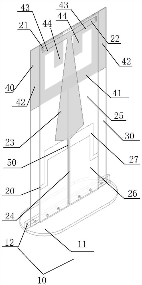
[0042] See figure 1 , a miniaturized airborne ultrashort wave antenna, comprising: a base 10, a first dielectric plate 20, a plurality of first through holes 21, a second dielectric plate 30, a first branch 22, a feed patch 23, and a microstrip feeder 24. Radiation patch 25, microstrip feeder floor 26, second stub 40 and ground stub 50. The bottom of the first dielectric board 20 is fixedly connected to the base 10 , the back of the first dielectric board 20 is attached to the front of the second dielectric board 30 , and the first dielectric board 20 and the second dielectric board 30 are concentric and coaxial. The airborne ultrashort wave antenna has an axisymmetric structure with the central vertical axis of the first dielectric plate 20 as an axisymmetric structure. The airborne ultrashort wave antenna has a symmetrical structure as a whole. Specifically, the radiation patch 25 and the microstrip feeder floor 26 are located on the back of the first dielectric board 20 a...


PUM


Abstract

The invention discloses a miniaturized airborne ultrashort wave antenna which comprises a base, a first dielectric plate, a plurality of first through holes, a second dielectric plate, a first branch knot, a feed patch, a micro-strip feeder line, a radiation patch, a micro-strip feeder line floor, a second branch knot and a grounding branch knot. The first dielectric plate is fixedly connected with the base, and the back surface is attached to the front surface of the second dielectric plate; the first branch knot, the feed patch, the microstrip feeder, the radiation patch, the microstrip feeder floor and the first through hole are all arranged on the first dielectric plate; the second branch knot and the grounding branch knot are arranged on the second dielectric plate. According to the present invention, the bandwidth of the antenna can be effectively widened, and the low-frequency gain is improved. The airborne ultrashort wave antenna is simple and compact in structure and small in size.

Description

technical field [0001] The invention belongs to the technical field of ultrashort wave antennas, in particular to a miniaturized airborne ultrashort wave antenna. Background technique [0002] Using ultrashort wave communication in a wide area, users hope that the communication channel will be smooth and confidential. However, they often encounter problems such as eavesdropping, electronic countermeasures, and channel congestion. Conventional short-wave radio stations use fixed frequencies to transmit and receive, which cannot avoid eavesdropping, artificial interference, and channel congestion. These problems must be completely overcome by frequency hopping technology. [0003] Frequency hopping technology is a common means of anti-jamming communication in the military. Compared with fixed frequency communication, frequency hopping communication is more concealed and difficult to be intercepted. As long as the other party does not know the law of carrier frequency hoppin...

Claims


Application Information

Patent Timeline
Patent Type & Authority Applications(China)
IPC IPC(8): H01Q9/04H01Q5/10H01Q5/20H01Q5/50H01Q1/48H01Q1/50H01Q1/00H01Q1/28
CPCH01Q9/0457H01Q5/10H01Q5/20H01Q5/50H01Q1/48H01Q1/50H01Q1/002H01Q1/285
Inventor 吴边卢宇锋张俊洁薛静怡
Owner XIDIAN UNIV
Why Eureka
Try Eureka