Eureka AIR delivers breakthrough ideas for toughest innovation challenges, trusted by R&D personnel around the world.

Laser cutting device

A laser cutting and laser head technology, applied in laser welding equipment, metal processing equipment, welding equipment, etc., can solve the problems of affecting the second surface processing, difficult to remove, affecting installation, etc., to improve cutting efficiency and improve cutting quality. Effect

Inactive Publication Date: 2021-11-02
ZHEJIANG JINAOLAN MASCH TOOL CO LTD
View PDF0 Cites 1 Cited by
  • Summary
  • Abstract
  • Description
  • Claims
  • Application Information

AI Technical Summary

Problems solved by technology

[0003] However, in production and manufacturing, it is usually necessary to open through holes on pipe fittings such as square pipes, rectangular pipes, etc. Some holes are non-standard round holes, which need to be processed by laser cutting. Process one side, then turn the pipe 180° and process the other side. At this time, the center of the through hole processed will be deviated due to the inaccurate positioning of the processing reference, which will affect the subsequent installation; and the slag will fall when processing the first side Adhesion formed on the inner wall of the tube is difficult to remove and affects the processing of the second surface

Method used


Image

  • Laser cutting device
  • Laser cutting device
  • Laser cutting device

Examples


Embodiment Construction

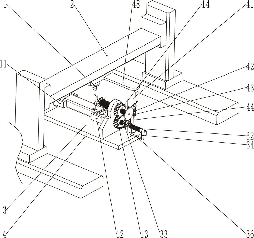
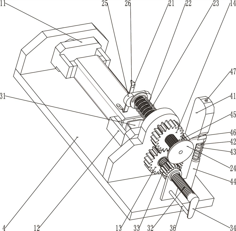
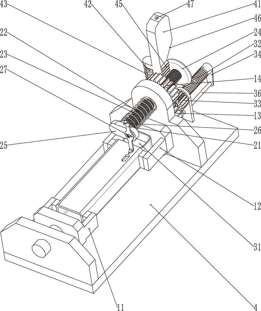
[0024] The present invention will be described in further detail below in conjunction with accompanying drawing and specific embodiment: see Figure 1-Figure 8 , laser cutting device, including laser head 1, mobile module 2 and fixture 3, described laser head 1 is located on mobile module 2, and described mobile module 2 is the moving device of existing laser head 2, all adopts PLC Control, this is the prior art, the clamp 3 is arranged below the laser head 2 and is used to position the pipe.

[0025] Described fixture 3 comprises frame 4, and described frame 4 is provided with driving collet 11 and driven collet 12, and the clamping mechanism between described driving collet 11, driven collet 12 and pipe fitting is existing. Some clamping chucks are not described in detail here. The active chuck 11 is provided with an active shaft, and the rotation of the active shaft is arranged on the frame 4. The active shaft is connected with a drive motor for driving The active shaft ro...


PUM


Abstract

The invention discloses a laser cutting device which comprises a laser head, a moving module and a clamp, wherein the clamp is provided with a positioning part used for positioning a pipe fitting, the clamp is provided with a reference device matched with the positioning part, the reference device is used for the laser head to accurately find the initial cutting position, and the positioning part is connected with the reference device through a transmission part. The laser cutting device is characterized in that a waste receiving device capable of storing cut waste is arranged in the positioning part, and a driving part which is matched with the moving module and can drive the reference device and the waste receiving device to move is arranged on the clamp. The invention provides the laser cutting device which accurately finds a cutting reference point during turnover cutting; and after cutting, waste is directly collected and cannot adhere to the inner wall of the pipe fitting, so that the cutting quality is improved while the cutting efficiency is improved.

Description

technical field [0001] The invention relates to the technical field of laser cutting equipment, in particular to a laser cutting device. Background technique [0002] The laser cutting machine focuses the laser light emitted from the laser device into a high power density laser beam through the optical path system. The laser beam irradiates the surface of the workpiece to make the workpiece reach the melting point or boiling point, and at the same time, the high-pressure gas coaxial with the beam blows away the molten or vaporized metal; the existing laser cutting machine is usually used to cut the plate. [0003] However, in production and manufacturing, it is usually necessary to open through holes on pipe fittings such as square pipes, rectangular pipes, etc. Some holes are non-standard round holes, which need to be processed by laser cutting. One side is processed, and then the other side is processed after turning the pipe 180°. At this time, the center of the through ...

Claims


Application Information

Patent Timeline
Patent Type & Authority Applications(China)
IPC IPC(8): B23K26/38B23K26/02B23K26/70
Inventor 吕时广金红英陈勇良张天伟王静郑群强王灵英叶建林
Owner ZHEJIANG JINAOLAN MASCH TOOL CO LTD
Why Eureka
Eureka Blog
Learn More