
Novel underground instrument antenna winding method

A technology of downhole instrument and winding method, applied in the field of downhole instrument antenna, can solve the problems of loose cover, large amount of work and high cost, and achieve the effects of reducing the amount of work, good self-lubrication and high firmness

Active Publication Date: 2021-11-02
GUOYI PETROLEUM TECH (WUXI) CO LTD
View PDF10 Cites 0 Cited by
  • Summary
  • Abstract
  • Description
  • Claims
  • Application Information

AI Technical Summary

Problems solved by technology

[0003] However, in the prior art, the traditional antenna coil outer cover is usually a detachable structure, which is convenient and simple to wind the antenna coil. Due to the harsh underground environment, the outer cover has a risk of loosening, requiring frequent maintenance, heavy workload, and high cost.

Method used


Image

  • Novel underground instrument antenna winding method
  • Novel underground instrument antenna winding method
  • Novel underground instrument antenna winding method

Examples


Embodiment Construction

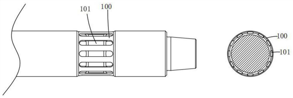
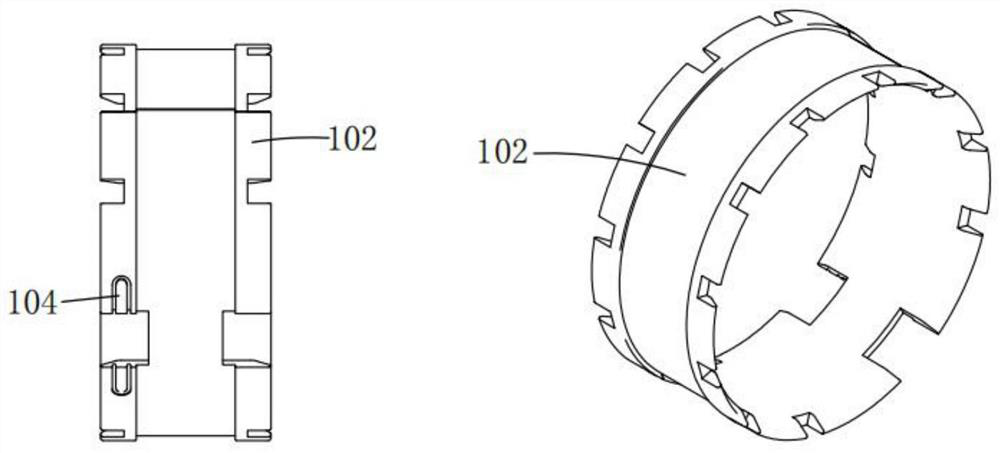
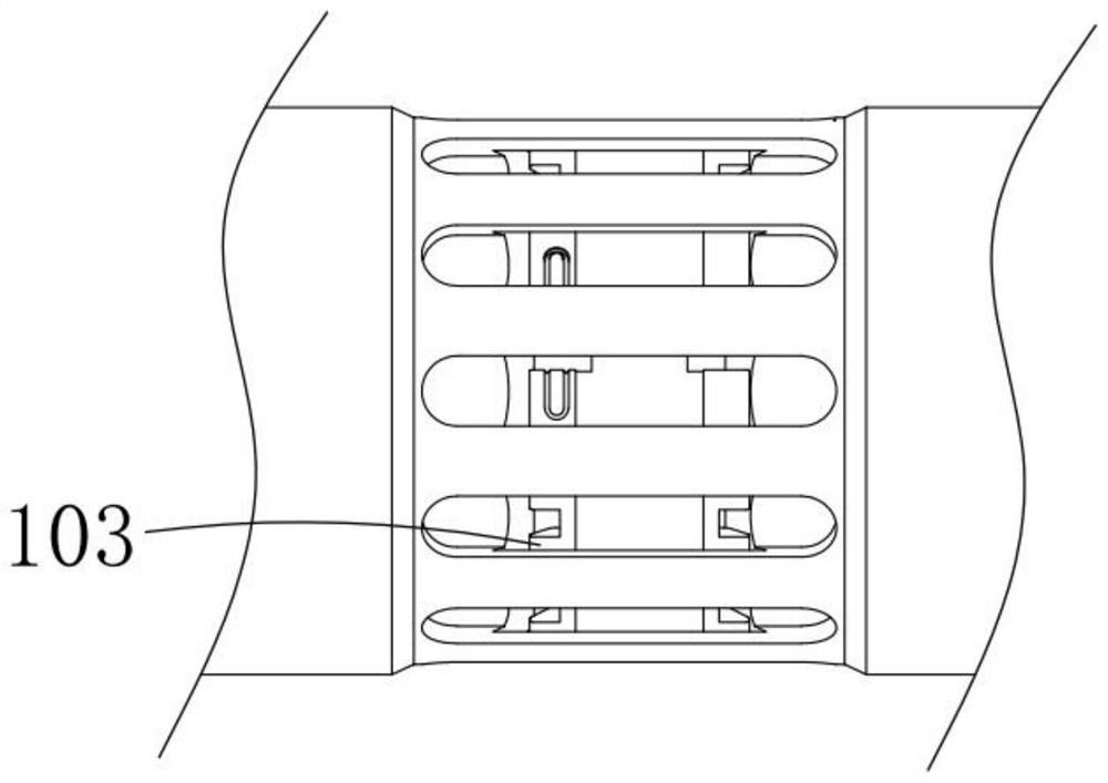
[0034] Please refer to figure 1 , figure 2 , image 3 , Figure 4 , Figure 5 and Figure 6 ,in, figure 1 It is a schematic diagram of the antenna slot in the present invention; figure 2 It is a schematic diagram of the skeleton in the present invention; image 3 It is a schematic diagram of the toggle gap in the present invention; Figure 4 It is a structural schematic diagram of the antenna cover drilling device in the present invention; Figure 5 It is a structural schematic diagram of the clamping mechanism in the present invention; Figure 6 It is a structural schematic diagram of the mobile assembly in the present invention. The new downhole instrument antenna winding method includes the following steps: S1, material preparation:

[0035] (1). Antenna housing main body 100, antenna coil, frame 102 and antenna fixing joint 104;

[0036] S2, process:

[0037] (1) Groove drilling: the antenna cover main body 100 is drilled through the antenna cover drilling de...


PUM


Abstract

The invention provides a novel underground instrument antenna winding method. The novel underground instrument antenna winding method comprises the following steps that S1, materials are prepared, specifically, (1) an antenna outer cover main body, an antenna coil, a framework and an antenna fixing joint are prepared; and S2, multiple working procedures are carried out, specifically, (1) grooves are drilled, specifically, drilling is carried out on the antenna outer cover main body through an antenna outer cover drilling device, so that an antenna outer cover groove and a plurality of antenna grooves are formed in the antenna outer cover main body by the antenna outer cover drilling device, and the plurality of antenna grooves are distributed in an annular array mode; (2) a notch is drilled, specifically, a framework is machined through equipment to form a shifting notch; and (3) fixing points are arranged, specifically, antenna fixing points are arranged on the framework. The novel underground instrument antenna winding method can adapt to the severe underground environment, and an antenna is assembled on the antenna outer cover main body through high-temperature heating, so that the firmness of the antenna is higher, and the risk of loosening is avoided so that the advantages of reducing the workload, the cost and the maintenance probability can be achieved.

Description

technical field [0001] The invention belongs to the technical field of downhole instrument antennas, and in particular relates to a novel winding method for downhole instrument antennas. Background technique [0002] At present, wireless measurement-while-drilling technology is the main direction of petroleum engineering technology development, and it is an advanced measurement instrument commonly used in international drilling. Wireless transmission mainly transmits electromagnetic waves through the antenna coil wound on the drill collar. Because the underground working environment has high temperature, high pressure, high corrosion, strong vibration, and high wear, the antenna coil is usually protected by an outer cover. [0003] However, in the prior art, the outer cover of the traditional antenna coil is usually a detachable structure, which is convenient and simple to wind the antenna coil. Due to the harsh underground environment, the outer cover has a risk of looseni...

Claims


Application Information

Patent Timeline
IPC IPC(8): B23P15/00H01F41/06
CPCB23P15/00H01F41/06
Inventor 刘森冯泽东耿标贺羽
Owner GUOYI PETROLEUM TECH (WUXI) CO LTD
Learn More