Integrated backfilling and pouring method for integral straight middle wall top of multi-arch tunnel

A multi-arch tunnel and integral technology, which is applied in the field of integrated backfilling and pouring of the integral straight middle wall and top of the multi-arch tunnel, can solve the problems of inability to ensure the compactness of the middle partition wall, unfavorable pressure transmission of the surrounding rock, and difficulty in realizing it. Achieve the effect of reducing the risk of cracks and water leakage, easy to control the construction quality, and reduce the difficulty of construction operation

Pending Publication Date: 2021-11-02
GUIZHOU HIGHWAY ENG GRP
View PDF1 Cites 1 Cited by
  • Summary
  • Abstract
  • Description
  • Claims
  • Application Information

AI Technical Summary

Problems solved by technology

[0010] (1) Due to the large width of the top area of ​​the partition wall, concrete is poured from the side of the first hole. If the cavity is not continuous and connected as a whole, it is difficult to completely fill the cavity by concrete pouring; in addition, the highest specific grouting hole At the top of the cavity with a higher point height, it is difficult to effectively fill and compact the highest point of the cavity by pouring concrete from the low point of the side, because the concrete pouring is different from the grouting grouting, and the concrete cannot be poured under high pressure. It can only be judged by whether the concrete can continue to be transported in, which is difficult to ensure the compactness at the highest point;
[0011] (2) It is mentioned in the patent that the poured concrete is vibrated and compacted, which is difficult to realize in actual operation, because the cavity at the top is usually small (if there is a large cavity, it will be necessary during the construction of the existing single-hole large arch tunnel) will be filled well), and after closing the formwork, the concrete is poured from the side formwork of the leading hole, and the plug-in vibrator cannot be used to vibrate and compact in layers. It can only vibrate the concrete adjacent to the side formwork area. In view of the large width of the top of the middle partition wall, if there are large cavities or string cavities, the concrete in most areas of the cavity cannot be backfilled and compacted. Difficult to compact
[0012] (3) In this patent, after the cavity at the top of the partition wall is backfilled with concrete, grouting is no longer performed. Usually, the rock and soil at the cavity are relatively weak and loose, and it is difficult for the concrete to be effectively mixed with the rock and soil to form a whole. That is to say, after the backfilling construction, the rock and soil in contact with the backfilling concrete is still weak, which still has an adverse effect on the transmission of surrounding rock pressure.
[0014] (1) When the backfilled hole slag is excavated in the back hole, it needs to be excavated and transported, which increases the construction cost;
[0015] (2) During the construction of the multi-arch tunnel, after the excavation of the first tunnel, in order to prevent the adverse effect of bias pressure on the partition wall and the stability of the tunnel as a whole, section steel or square wood should be used to support the partition wall on the side of the rear tunnel. The slag backfilling of the rear tunnel will cause cross interference with the support construction of the middle partition wall, which is inconvenient for construction
[0016] In summary, this patented technology cannot guarantee the compactness of the backfill on the top of the partition wall, and cannot ensure that the pressure of the surrounding rock is evenly and stably transmitted to the partition wall
This patent is more suitable for the backfilling of cavities such as karst caves encountered by the roof of the conventional separated tunnel during the excavation process. It is not applicable to the key process of backfilling the top of the partition wall and the core stress node.

Method used


Image

  • Integrated backfilling and pouring method for integral straight middle wall top of multi-arch tunnel
  • Integrated backfilling and pouring method for integral straight middle wall top of multi-arch tunnel
  • Integrated backfilling and pouring method for integral straight middle wall top of multi-arch tunnel

Examples


Embodiment 1

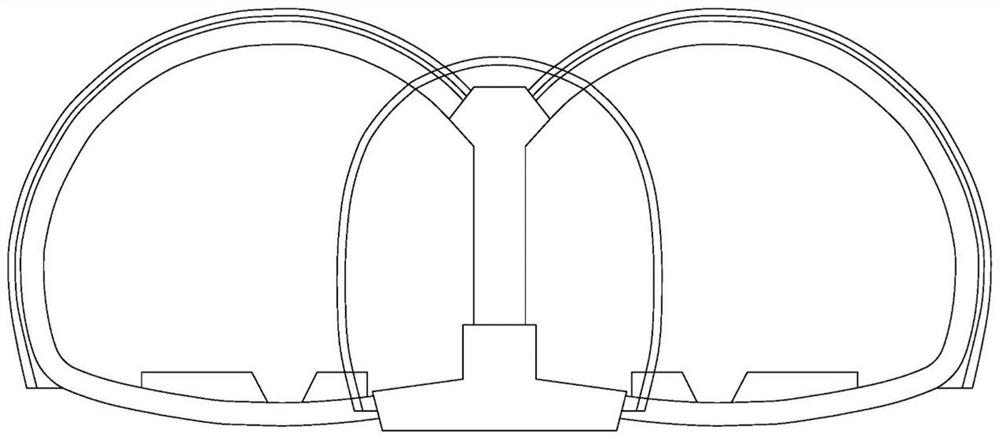
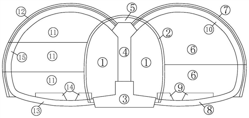
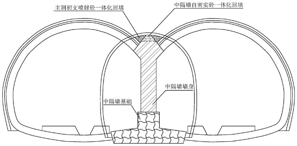
[0054] Embodiment 1 of the present invention: an integrated backfill pouring method for the integral straight middle wall and top of the multi-arch tunnel, which divides the space between the top of the middle partition wall and the initial support vault of the middle pilot tunnel into three areas, namely the top of the wall For the trapezoidal area and the triangular areas on both sides, after the foundation of the middle partition wall is poured, the trapezoidal area of ​​the middle partition wall and the top of the wall will be poured to the vault of the middle pilot tunnel at one time. After the middle partition wall is poured, the main hole will be constructed. The integrated shotcrete backfilling construction of the area and the primary support of the main cave is reinforced by grouting with steel flower tubes, and the pouring of the middle partition wall and the top of the wall is completed. In order to prevent the possible lack of compactness in the integrated backfill ...


PUM


Abstract

The invention discloses an integrated backfilling and pouring method for an integral straight middle wall top of a multi-arch tunnel, which is characterized in that a space between a middle partition wall top and a middle pilot tunnel initial supporting vault is divided into three areas, namely a wall top trapezoid area and triangular areas on the two sides; a middle partition wall body and a wall top trapezoid area are poured to a middle pilot tunnel vault at a time after a middle partition wall foundation is poured; main tunnel construction is conducted after a middle partition wall is poured; the triangular areas on the two sides of the wall top and a main tunnel primary support are subjected to integrated sprayed concrete backfill construction; steel floral tubes are adopted for supplementary grouting reinforcement; and pouring of the middle partition wall body and the wall top is completed. According to the invention, the problems that concrete of the wall cap of the middle partition wall is not vibrated compactly due to the fact that the construction space of the wall top is extremely limited in a conventional construction method, and the strength is insufficient are solved. The safety of main hole excavation construction is ensured. The integral structure formed by the middle partition wall and the main tunnel primary support is better in integrity. The risks of cracks and water leakage of the middle partition wall can be effectively reduced.

Description

technical field [0001] The invention relates to concrete, in particular to an integrated backfill pouring method for an integral straight middle wall and top of a multi-arch tunnel. Background technique [0002] In the construction of expressways in mountainous areas, due to the large undulations of the terrain, it is more and more common to use suspension bridges, cable-stayed bridges and tunnels to connect bridges and tunnels across canyons and mountains. Due to the problem of the alignment design of the bridge and the highway, the end of the tunnel connected to the super-large bridge is mostly in the form of a multi-arch tunnel, and it will gradually transition to a separate tunnel after entering a certain length of the mountain, which makes the application of multi-arch tunnels in expressway projects more and more difficult. more and more common. Usually, the initial section of multi-arch tunnels connected by bridges and tunnels, in order to meet the linear design stand...

Claims


Application Information

Patent Timeline
Patent Type & Authority Applications(China)
IPC IPC(8): E21D9/00E21D9/14E21D11/10E21F16/02
CPCE21D9/00E21D9/14E21D11/10E21D11/105E21F16/02
Inventor 龙立敦李少方王朝国周旭林文凯张凯潘鑫
Owner GUIZHOU HIGHWAY ENG GRP
Why Eureka
Try Eureka