Progressive pipeline type sintering furnace

A pipeline type, sintering furnace technology, applied in the direction of furnace, charge, furnace type, etc., can solve the problems of complex continuous moving mechanism, large floor space, high installation cost and high use cost, and achieve low modification cost and floor space. Small, good promotional effect

Pending Publication Date: 2021-11-02
徐州中辉光伏科技有限公司
View PDF6 Cites 1 Cited by
  • Summary
  • Abstract
  • Description
  • Claims
  • Application Information

AI Technical Summary

Problems solved by technology

Common continuous sintering furnaces mainly include mesh belt furnaces and push rod sintering furnaces. No matter which one is used, it occupies a large area and has a slightly complicated continuous moving mechanism, which makes the installation cost and use cost relatively high. high

Method used


Image

  • Progressive pipeline type sintering furnace
  • Progressive pipeline type sintering furnace
  • Progressive pipeline type sintering furnace

Examples


Embodiment Construction

[0023] The technical solutions provided by the present invention will be described in detail below in conjunction with specific examples. It should be understood that the following specific embodiments are only used to illustrate the present invention and are not intended to limit the scope of the present invention.

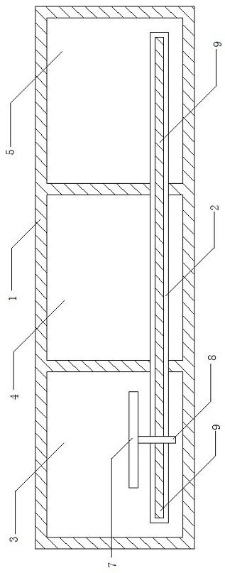
[0024] Such as figure 1 Shown is a structural schematic diagram of the present invention, the present invention is a progressive pipeline type sintering furnace, comprising a pipeline type furnace body 1, a pushing guide rail 2 arranged axially along the pipeline type furnace body 1 and a Progressive push pieces.

[0025] The front and rear ends of the tubular furnace body 1 are the furnace body inlet and the furnace body outlet respectively, and the interior of the tubular furnace body 1 is a preheating section 3 , a high temperature section 4 and a cooling section 5 from front to back.

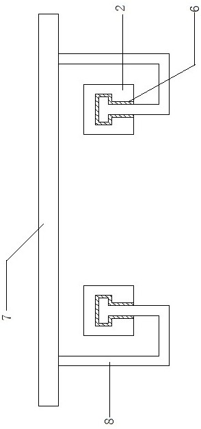
[0026] The surface of the pushing guide rail 2 is provided with a pushing...


PUM


Abstract

The invention provides a progressive pipeline type sintering furnace. The progressive pipeline type sintering furnace comprises a pipeline type furnace body, a pushing guide rail arranged in the axial direction of the pipeline type furnace body and a progressive pushing piece installed on the pushing guide rail in a matched mode, wherein a furnace body inlet and a furnace body outlet are formed in the front end and the rear end of the pipeline type furnace body respectively, and a preheating section, a high-temperature section and a cooling section are sequentially arranged in the pipeline type furnace body from front to back; a pushing groove is formed in the surface of the pushing guide rail in the length direction; and the progressive pushing piece is installed in the pushing groove in a matched mode and comprises a pushing plate, a pushing frame and a pushing rod. The novel continuous sintering furnace provided by the invention is provided with the pipeline type furnace body, so that the occupied area is small; the innovative progressive pushing piece is arranged, staying and continuous moving of the pushing plate are achieved through the electricity-to-magnetism principle, and the whole sintering process is made to be more flexible; and the functional structure is effectively simplified, modification can be directly carried out in an existing furnace body, the modification cost is low, and good popularization practicability is achieved.

Description

technical field [0001] The invention belongs to the technical field of photovoltaics and specifically designs a progressive pipeline type sintering furnace. Background technique [0002] The sintering furnace refers to the special equipment for obtaining the required physical and mechanical properties and microstructure of the powder compact through sintering. The sintering furnace is used to dry the slurry on the silicon wafer, remove the organic components in the slurry, and complete the sintering of the aluminum back field and the grid line. It is one of the important production and processing equipment in photovoltaic technology. [0003] The current sintering furnaces can be divided into two categories according to the different moving modes, continuous sintering furnaces and batch sintering furnaces. Common continuous sintering furnaces mainly include mesh belt furnaces and push rod sintering furnaces. No matter which one is used, it occupies a large area and has a sl...

Claims


Application Information

Patent Timeline
Patent Type & Authority Applications(China)
IPC IPC(8): F27B9/02F27B9/12F27B9/22F27B9/30
CPCF27B9/028F27B9/12F27B9/22F27B9/30F27B2009/122F27B2009/124F27M2003/04
Inventor 周淼生华强季晖
Owner 徐州中辉光伏科技有限公司
Why Eureka
Try Eureka