
Electrodialysis electrode water plate water pressure test tool and detection method

A technology of hydrostatic testing and extreme water plate, applied in the field of electrodialysis, can solve the problems of disassembly, existence of risks, inability to repair and replace, etc., to achieve the effect of improving work efficiency, avoiding workload, and avoiding leakage risks

Active Publication Date: 2021-11-02
浙江艺谛环境设备有限公司
View PDF12 Cites 0 Cited by
  • Summary
  • Abstract
  • Description
  • Claims
  • Application Information

AI Technical Summary

Problems solved by technology

[0006] To sum up, there are two detection methods of the polar water plate, but they all have the same problem, that is, only when the polar water plate is installed on the equipment It can be tested, and when there is a leak in the welding of the polar water plate, the equipment must be disassembled before maintenance or replacement
[0007] The first method, although it is convenient for replacement and maintenance in the factory, but the test water pressure is low, which cannot meet the actual operating water pressure, even if there is no leakage under low water pressure points, but in actual use, there are still risks
[0008]The second method, once leakage of the polar water plate is found, it cannot be repaired or replaced on site, and can only be returned to the factory for repair or a new polar water plate will be sent to on site
Firstly, on-site man-hours are wasted, and secondly, there is still a risk of leakage of the electrode plate after repair or replacement

Method used


Image

  • Electrodialysis electrode water plate water pressure test tool and detection method
  • Electrodialysis electrode water plate water pressure test tool and detection method
  • Electrodialysis electrode water plate water pressure test tool and detection method

Examples


Embodiment Construction

[0023] DRAWINGS Examples and further detailed description of the present invention, the following Examples are intended to explain the present invention and the present invention is not limited to the following embodiments.

[0024] Example.

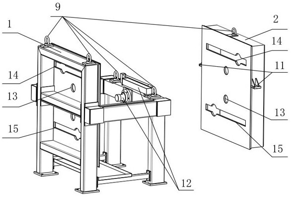
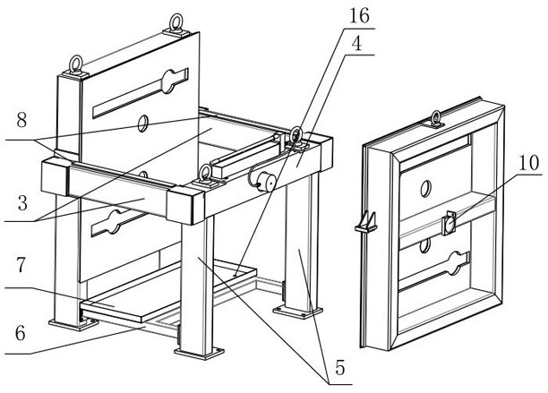
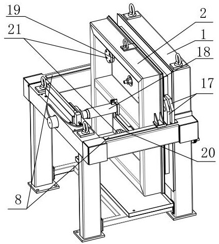
[0025] See Figure 1 to 4 , The present embodiment electrodialysis embodiment electrode plate water pressure test fixture includes a fixed-side bearing frame 1, frame 2 swimming pressing side, two load-bearing beams 3, the front end of cross member 4, two support legs 5 and the front end of the bottom cross beam 6, water tray 7, a slider 8, the bail 9, the pressing block floating center of the top side of the seat 10, traveling block 11 and the lug 12 of the hydraulic pressing mechanism.

[0026] like Figure 1 - Figure 2As shown, the fixed side pressure frame 1 in the present embodiment is provided with a support pin on both sides, and there are two hanging ring 9, and both sides are connected to one end of the two load beams 3; the front end...


PUM


Abstract

The invention relates to an electrodialysis electrode water plate water pressure test tool and a detection method, and belongs to the field of electrodialysis. The device comprises a fixed side pressure-bearing frame, bearing cross beams, a front end cross beam, front end cross beam supporting legs, a bottom beam, a water pan, a sliding plate, a hanging ring and a hydraulic pressing mechanism, the two sides of the fixed side pressure-bearing frame are connected with one ends of the two bearing cross beams, and the two sides of the front end cross beam are connected with the other ends of the two bearing cross beams; and two front end cross beam supporting legs are connected below the front end cross beam, a bottom beam is connected with self-supporting legs on the two sides of the fixed side pressure-bearing frame and the two front end cross beam supporting legs, a water pan is arranged on the bottom beam, a sliding plate is arranged on the bearing cross beam, hanging rings are arranged on the fixed side pressure-bearing frame, the front end cross beam and the moving side pressing frame, and a hydraulic pressing mechanism is arranged on the front end cross beam. The ex-factory quality of the electrodialysis equipment is improved, the problem that the leakage risk still exists due to leakage of the electrode water plate and after maintenance or replacement is avoided, unnecessary workload is avoided, and the working efficiency is improved.

Description

Technical field [0001] The present invention relates to a tooling and a method for detecting, particularly, to a pole electrodialysis water pressure test tooling plate and testing methods, which belongs to the technical field electrodialysis. Background technique [0002] Electrodialysis technology is one of the early development and made significant achievements in industrial membrane separation technology. Early studies dating back two centuries ago. Most historical reports are from 1748 French scholar A. Noller first discovered water through the bladder membrane naturally spread to the start of the experiment the ethanol solution. The experiments confirmed the discovery and the phenomenon of water penetration through the animal membrane. 1854 Graham discovered the phenomenon of dialysis. 1863 Dubrunfaut a film made of the first dialyzer, successfully separating the sugar salts. Morse and the 1903 Pierce two electrodes are respectively located inside and outside the dialysis ba...

Claims


Application Information

Patent Timeline
IPC IPC(8): G01N15/08
CPCG01N15/082Y02A20/124
Inventor 王大新施小林杨鹏
Owner 浙江艺谛环境设备有限公司
Learn More