A visual pipe fitting blockage mechanism and its blockage method

A technology for pipe fittings and pipelines, applied in the field of blocking devices, can solve problems such as danger, block position deviation, energy waste, etc., and achieve the effects of saving processes and manpower, reducing the error rate of plugging, and improving the efficiency of plugging

Active Publication Date: 2016-04-13
BEIJING GAS GRP
View PDF7 Cites 0 Cited by
  • Summary
  • Abstract
  • Description
  • Claims
  • Application Information

AI Technical Summary

Problems solved by technology

At present, a method of adding branch pipelines without stopping the gas transmission is to weld a connecting pipe fitting on the gas transmission pipeline. The upper port of the pipe fitting has a blocking seat, and a splint valve and splint for isolation are installed above the blocking seat. A hole tapping machine is installed above the valve, and the branch pipeline is connected with the side wall of the wiring pipe fittings, and then the hole tapping machine is used to make holes in the gas pipeline. The plugging device lowers the plugging disc into the plugging seat through the splint valve. After the lower plugging is completed, the plugging disc needs to be fixed. The existing plugging technology has the following technical problems: 1. When the plugging is plugged, the position of the plugging may shift , or impurities such as iron filings in the lower blocker will also hinder the blockage movement. At this time, the blockage will be stuck. The operator cannot see the specific reason and where the failure occurs. The operator can only rely on experience Deal with this situation; 2. When fixing the blockage, the operator cannot visually see the position of the blockage and the status of the plugging, and can only fix it by experience. There are problems that the blockage is not fixed properly and the gas inside the pipeline leaks; 3. By Fixing from outside to inside, that is, opening a plurality of screw holes on the outer peripheral surface of the plugging seat, and then fixing the plugging plate in the plugging seat through the screws through the screw holes. On the one hand, this fixing method needs to open screw holes, which is time-consuming and laborious; 4. Opening Multiple screw holes can cause air leakage, especially when the plugging disc is not placed correctly, the gas inside the fluid pipe will leak out through the screw holes, which is extremely dangerous when doing electric welding, and also causes waste of energy

Method used


Image

  • A visual pipe fitting blockage mechanism and its blockage method
  • A visual pipe fitting blockage mechanism and its blockage method
  • A visual pipe fitting blockage mechanism and its blockage method

Examples


Embodiment Construction

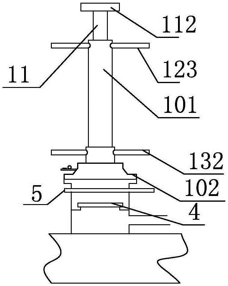
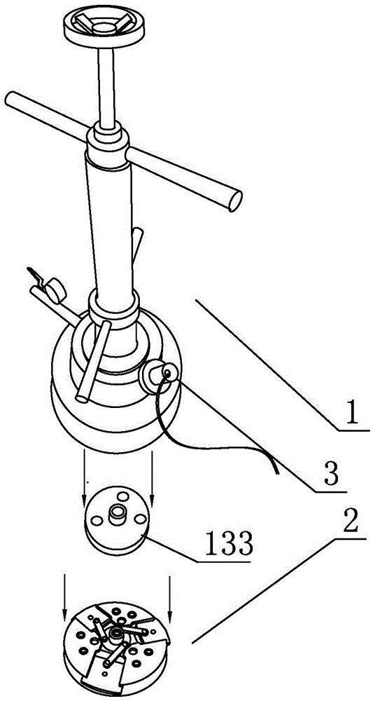
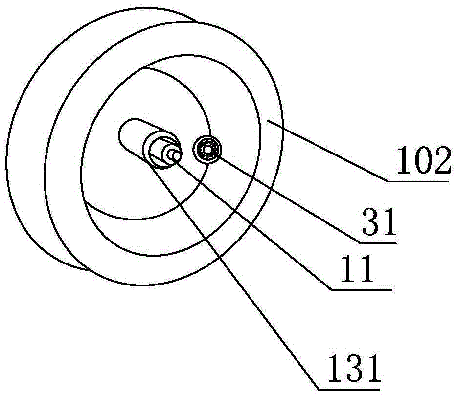
[0031] Such as Figure 1-5 As shown, the visualized pipe fitting plugging 2 mechanism of this embodiment includes a lower blocking device 1 and a plugging device 2, the lower blocking device 1 is used to place the plugging device 2 in the flange plugging seat 4 on the pipe fitting, and the lower blocking device 1 includes a housing 101 , the transmission rod 11 installed in the housing 101, the lifting device 12 for lifting the transmission rod 11, the separation connection device 13 for separating and connecting the plug 2, and the lower plug connecting box 102 fixedly connected with the housing 101, characterized in that: The lower block connecting box 102 is equipped with a monitoring device 3 for monitoring the movement of the lower blocking block 2 . Surveillance equipment 33, fixed seat 32 comprises camera fixture 321, connects the connection seat 322 of fixed camera fixture 321 and wire joint 323, and the side upper part of connecting box 102 has the through hole that i...


PUM


Abstract

The invention discloses a visual pipe fitting blockage mechanism. The mechanism comprises a blockage device and a block, wherein the blockage device is used for placing the block in a flange blockage seat on a fitting and comprises a shell, a transmission rod, a lifting device, a separating and connecting device and a blockage connecting box; the transmission rod is arranged in the shell; the lifting device is used for lifting the transmission rod; the separating and connecting device is used for separating and connecting the block; the blockage device connecting box is fixedly connected with the shell and is provided with a monitoring device for monitoring the blockage movement of the block; the monitoring device comprises a camera, a fixed seat and monitoring equipment; the camera is arranged in the blockage connecting box; the fixed seat is used for fixedly arranging the camera; the monitoring equipment is connected with the camera. The visual pipe fitting blockage mechanism realizes pipeline blockage from inside to outside, a process for punching in the blockage seat and the labor are saved, blockage is performed under a visual condition, the mechanism is safer and more reliable, and the risk that gas leaks from a screw hole is avoided.

Description

technical field [0001] The invention relates to a plugging device for a non-stop fluid pipeline down-blocking device, in particular to a special device for plugging a fluid pipeline after opening a hole without a non-stop operation. Background technique [0002] In order to transport gas such as natural gas and coal gas, it is often necessary to add branch pipelines to the already laid and in-use gas transmission pipelines. In order not to affect the normal gas transmission of the gas transmission pipelines, it is necessary to add branch pipelines without stopping the gas transmission. pipeline. At present, a method of adding branch pipelines without stopping the gas transmission is to weld a connecting pipe fitting on the gas transmission pipeline. The upper port of the pipe fitting has a blocking seat, and a splint valve and splint for isolation are installed above the blocking seat. A hole tapping machine is installed above the valve, and the branch pipeline is connected...

Claims


Application Information

Patent Timeline
Patent Type & Authority Patents(China)
IPC IPC(8): F16L55/10
CPCF16L55/10
Inventor 李夏喜吴国荣陈文利罗强晋铁汉张海云高岷
Owner BEIJING GAS GRP
Why Eureka
Try Eureka