Coating spraying equipment for civil engineering building professional decorative plate
A technology for decorative panels and civil engineering, applied in the direction of coating, spraying devices, and devices for coating liquid on the surface, can solve the problems of increasing the labor intensity of workers, speeding up the spraying efficiency, and not being able to spray the panels, so as to reduce labor costs. Strength, good drying effect, and quality-enhancing effect
- Summary
- Abstract
- Description
- Claims
- Application Information
AI Technical Summary
Problems solved by technology
Method used
Image
Examples
Embodiment 1
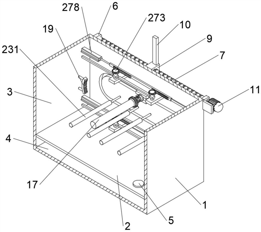
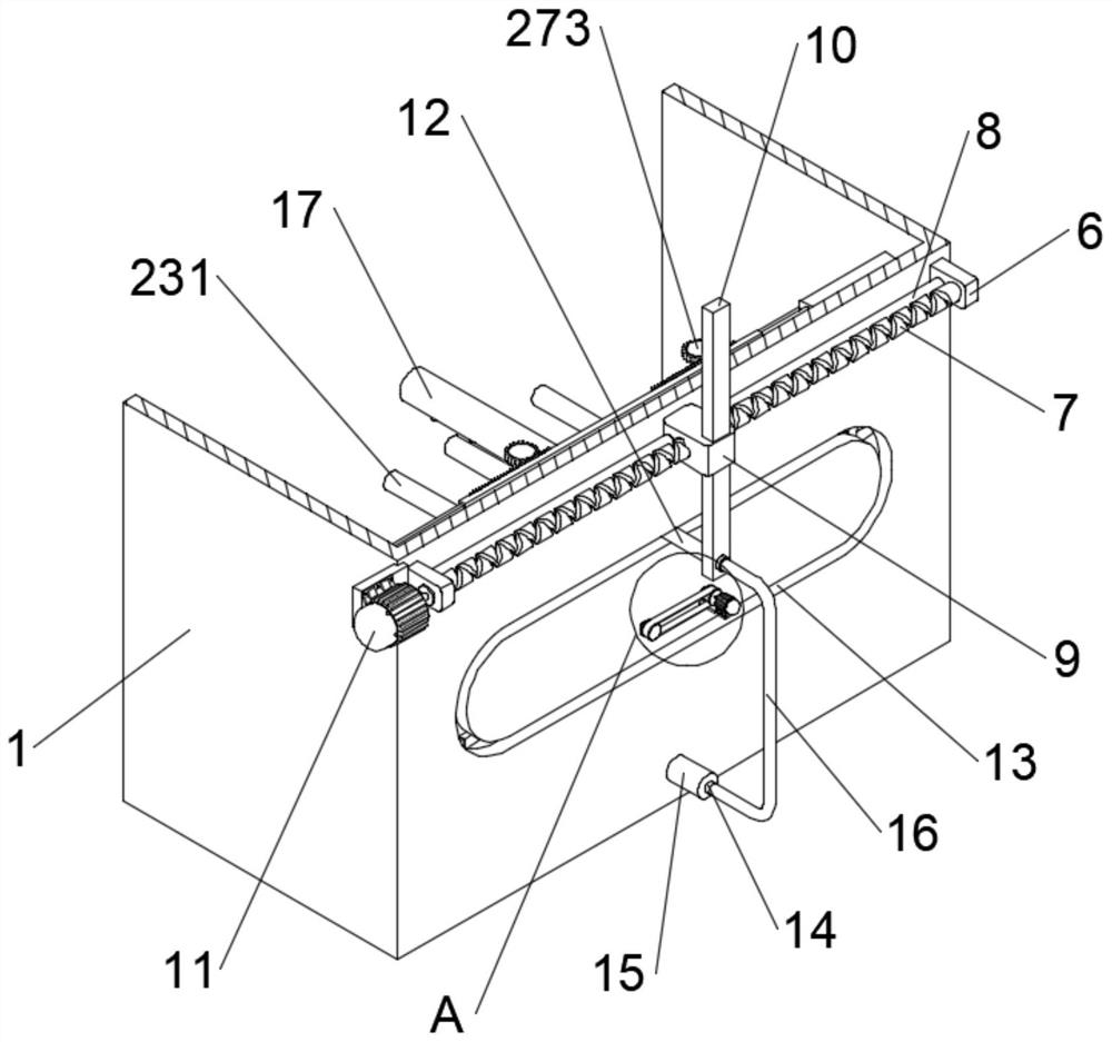
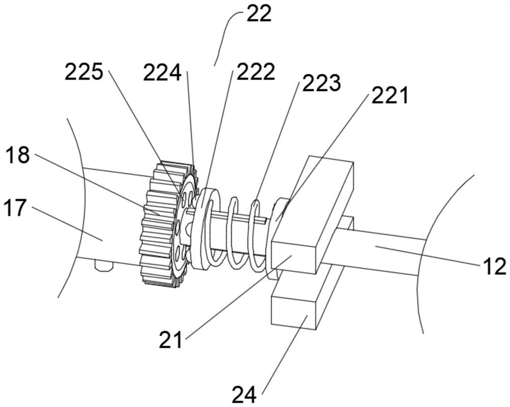
[0036]In this embodiment, as shown in Figures 1-9, a paint spraying equipment for professional decorative panels in civil engineering and construction includes a box body 1 with an unclosed front end, and the inner wall of the box body 1 is arranged from top to bottom through a partition 2 Spraying chamber 3 and material storage chamber 4, feed pipe 5 is installed on the front side of the top of dividing plate 2, the bottom of feed pipe 5 communicates with material storage chamber 4, and the top of feed pipe 5 is provided with sealing cover. The front end of the box body 1 is provided with a side door corresponding to the upper side of the partition plate 2, and the side door is provided with a visible opening. The middle part of the rear side wall of the spraying chamber 3 is provided with an annular slideway 13, and the rear end of the box body 1 corresponds to the slideway. The upper position of the road 13 is connected with a reciprocating screw 7 by rotating the support bl...
Embodiment 2
[0039] On the basis of Embodiment 1, the material storage chamber 4 is provided with two sets of stirring mechanisms 26, which are attracted by the gravitational component two between the stirring mechanisms 26 and the connecting pipe 12, and each set of stirring mechanisms 26 includes vertically penetrating The vertical bar 261 that is slidably connected to the rear side section of the partition plate 2, the bottom end of the vertical bar 261 is provided with a cavity 262, and a slide bar 264 with a rectangular cross section is slidably connected in the cavity 262, and the bottom end of the slide bar 264 is connected to the box body The bottom wall of 1 is fixed, and a spring 2 263 is fixed between the top of the slide bar 264 and the top wall of the cavity 262, and a horizontal plate 265 is fixed at the position where the front end of the vertical bar 261 is located in the storage chamber 4. Attraction component two includes the iron block two 24 that is fixed on the bottom e...
Embodiment 3
[0041] On the basis of Embodiment 2, the inner wall of the spraying chamber 3 is located at the upper and lower sides of the slideway 13, and two groups of drying mechanisms 27 are provided. Two supporting bases 271, the tops of the two supporting bases 271 are rotatably connected with a rotating column 272, the tops of the two rotating columns 272 are fixed with a gear 273, and the rear ends of the two gears 273 are meshed with the same gear bar 274, One end of gear rod 274 is slidingly connected with positioning rod 275, and the other end of positioning rod 275 is fixed with the side wall of spraying chamber 3, and the other end of gear rod 274 is connected with hydraulic rod 278, and hydraulic rod 278 is connected with the other side wall of spraying chamber 3. The side walls are fixed, and the outer walls of the two rotating columns 272 are provided with electric heating rods 277 . The outer wall of the rotating column 272 is located between the second gear 273 and the sup...
PUM
 Abstract
Description
Claims
Application Information
 - R&D
- Intellectual Property
- Life Sciences
- Materials
- Tech Scout
- Unparalleled Data Quality
- Higher Quality Content
- 60% Fewer Hallucinations
Browse by: Latest US Patents, China's latest patents, Technical Efficacy Thesaurus, Application Domain, Technology Topic, Popular Technical Reports.
© 2025 PatSnap. All rights reserved.Legal|Privacy policy|Modern Slavery Act Transparency Statement|Sitemap|About US| Contact US: help@patsnap.com


