Supercharge Your Innovation With Domain-Expert AI Agents!

Automobile hub clamp, machining equipment and production line

A technology of automobile wheel hub and processing equipment, applied in metal processing equipment, metal processing, metal processing mechanical parts, etc., can solve the problems of low processing accuracy, high processing cost, cutting fluid splash, etc., to ensure accuracy and quality, contact area Guarantee and reduce the effect of waste of resources

Active Publication Date: 2021-11-05
QINGDAO TECHNOLOGICAL UNIVERSITY +1
View PDF12 Cites 2 Cited by
  • Summary
  • Abstract
  • Description
  • Claims
  • Application Information

AI Technical Summary

Problems solved by technology

However, during the processing process, the pouring type will cause the cutting fluid to splash due to the large amount of pouring cutting fluid. Because the workers operate the machine tool, the cutting fluid will affect the health of the workers, and the cutting fluid is extremely harmful to the environment and the processing cost is extremely high. , increasing the cost
Moreover, hub island machining does not distinguish between rough machining, semi-finishing machining, and finishing machining, so that their positioning datums are the same, resulting in lower machining accuracy
[0005] For the wheel hub processing production line, in addition to the problems of fixture positioning and machining links, there are also problems such as the inability to effectively connect the loading and unloading process, and the small number of wheels transported at one time, resulting in the production line failing to meet the quality and efficiency requirements of the wheels.

Method used


Image

  • Automobile hub clamp, machining equipment and production line
  • Automobile hub clamp, machining equipment and production line
  • Automobile hub clamp, machining equipment and production line

Examples


Embodiment 1

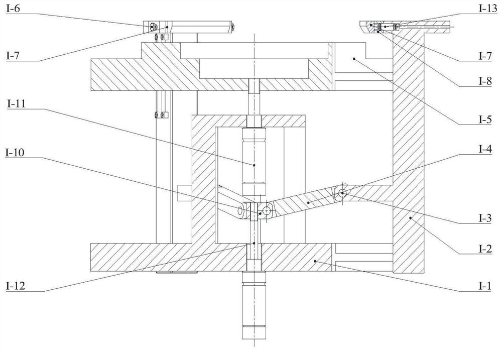
[0058] This embodiment provides a kind of automobile wheel clamp, as Figure 1-Figure 3 As shown, it includes a clamp main body and a positioning device I-5, the positioning device I-5 is used for positioning the hub V, and the clamp main body is used for clamping the hub V.

[0059] Specifically, the clamp body includes a fixed platform I-1, a clamping claw I-2, a linkage mechanism, etc., and multiple clamping claws I-2 are installed along the circumference of the fixed platform I-1, and the clamping claw I-2 is connected The rod mechanism is connected with the cylinder I-12, and the connecting rod mechanism is driven by the cylinder I-12 to make the clamping claw I-2 clamp or loosen the hub V.

[0060] Further, such as Figure 4-Figure 6 As shown, the fixed platform I-1 is used to connect the spindle of the machine tool, and multiple installation grooves are evenly opened in its circumference, and the two sides of the installation groove are symmetrically installed on the t...

Embodiment 2

[0072] This embodiment provides an automobile hub clamp, including a clamp body and a positioning device I-5, the positioning device I-5 is used for positioning the wheel hub V, and the clamp body is used for clamping the wheel hub V. Wherein, the main structure of the fixture is the same as that of the first embodiment, and will not be repeated here.

[0073] Such as Figure 9 and Figure 10 As shown, the positioning device 1-5 includes a movable platform 1-5-2 and a positioning module, and the positioning module includes a positioning block 1-26, a cylinder 1-27, a first connecting rod 1-28, a second connecting rod 1-25, etc. , the shape of the movable platform I-5-2 is adapted to the fixed platform I-1, and the circumferential direction of the movable platform I-5-2 is corresponding to the installation groove of the fixed platform I-1. The installation groove of 2 forms mobile pair with movable part 1-9.

[0074] In this embodiment, the movable platform I-5-2 is set in t...

Embodiment 3

[0078] This embodiment provides an automobile hub clamp, including a clamp body and a positioning device I-5, the positioning device I-5 is used for positioning the wheel hub V, and the clamp body is used for clamping the wheel hub V. Wherein, the main structure of the fixture is the same as that of the first embodiment, and will not be repeated here.

[0079] Such as Figure 11 Shown, positioning device 1-5 comprises movable platform 1-5-3 and positioning module, and positioning module comprises positioning plate 1-31, spring 1-34, and the shape of movable platform 1-5-3 is similar to fixed platform 1-1. To adapt, the movable platform I-5-3 is set to a truncated cone shape, and its raised part is used to be inserted into the V inner ring of the hub. Movable platform I-5-3 circumferential direction is corresponding to the installation groove of fixed platform I-1 and offers installation groove equally, and the installation groove of movable platform I-5-3 forms mobile pair wi...


PUM


Abstract

The invention discloses an automobile hub clamp, machining equipment and a production line. According to the technical scheme, the automobile hub clamp comprises a clamp body and a positioning device, the clamp body comprises a fixed platform and a plurality of clamping claws arranged in the circumferential direction of the fixed platform at intervals, and the clamping claws are used for clamping an outer ring of a hub. The multiple clamping claws are connected with a driving piece through a connecting rod mechanism, and the clamping claws can move in the radial direction of the fixed platform under the action of the driving piece. The positioning device comprises a movable platform connected with the clamping claws in a sliding mode, and the movable platform is provided with a positioning module used for positioning the inner ring or the outer ring of the hub. The machining equipment comprises a clamp, a machine tool and a minimum quantity lubricating device. The production line comprises the machining equipment, a feeding system, a feeding and discharging mechanical arm and a discharging roller way. The clamp can adapt to clamping of hubs of various sizes and specifications. Minimum quantity lubrication machining is embedded into machining, the requirement of hub machining can be met, and the machining quality is guaranteed; and effective hub connection is achieved from blank conveying to machining output, and the machining efficiency is improved.

Description

technical field [0001] The invention relates to the technical field of wheel hub processing, in particular to an automobile wheel hub fixture, processing equipment and a production line. Background technique [0002] Automobile wheels are developing in the direction of diversification and individualization. Therefore, a wheel hub production mode with multiple specifications, multiple sizes, and variable batches has been formed. For the hubs of different specifications and sizes, different processing equipment is often required to meet their processing needs. As the types of hubs increase, the demand for equipment also increases. Hub fixture is a necessary tool for hub processing, which has a very important impact on the production efficiency and production quality of the hub processing production line. [0003] The inventors found that the current hub fixtures have problems such as positioning accuracy that cannot meet the processing requirements, and cannot adapt to the pr...

Claims


Application Information

Patent Timeline
Patent Type & Authority Applications(China)
IPC IPC(8): B23Q3/08B23Q7/04
CPCB23Q3/08B23Q7/04B23Q3/062B23Q11/1046B23B5/02B23B31/16195B23B31/16216B23Q3/082B23B2215/08B05B13/0221
Inventor 李长河陈民凯周宗明张乃庆徐帅强刘德伟卢秉恒张彦彬王晓铭杨敏刘波崔歆刘明政吴喜峰
Owner QINGDAO TECHNOLOGICAL UNIVERSITY
Features
  • R&D
  • Intellectual Property
  • Life Sciences
  • Materials
  • Tech Scout
  • Unparalleled Data Quality
  • Higher Quality Content
  • 60% Fewer Hallucinations
Learn More