
Metal dot matrix reinforced ablative material sandwich plate structure

A metal lattice and ablation material technology, which is applied in the direction of metal layered products, layered products, aerospace safety/emergency devices, etc., can solve problems such as poor reliability, low strength and fracture toughness, and risk of interface connection. Achieve the effect of eliminating the risk of failure, slowing down the mass ablation rate, and realizing the structure lightweight

Pending Publication Date: 2021-11-05
SHANGHAI AEROSPACE SYST ENG INST
View PDF8 Cites 1 Cited by
  • Summary
  • Abstract
  • Description
  • Claims
  • Application Information

AI Technical Summary

Problems solved by technology

The main problems of this type of TPS are: (1) the low density of ablation materials develops rapidly, and the matching load-bearing structure has a single form, and there is a large space for weight reduction; (2) the interface between ablation materials and load-bearing structures Connections (adhesive or mechanical) are at risk of failure in harsh thermal environments and are not reliable
The main problems of this type of ITPS are: (1) The strength and fracture toughness of high-temperature ceramic materials are lower than those of high-performance alloys, and the lightweight advantage of the sandwich structure of high-temperature ceramic materials is not obvious from a mechanical point of view; (2) The thermal bridge effect is The heat transfer characteristics shared by the lattice sandwich structure, the method of filling the insulation material or superimposing the insulation layer will cause the above-mentioned interface connection risk

Method used


Image

  • Metal dot matrix reinforced ablative material sandwich plate structure
  • Metal dot matrix reinforced ablative material sandwich plate structure
  • Metal dot matrix reinforced ablative material sandwich plate structure

Examples


Embodiment Construction

[0027] The metal lattice reinforced ablative material sandwich plate structure proposed by the present invention will be further described in detail below in conjunction with the accompanying drawings and specific embodiments. The advantages and features of the present invention will be apparent from the following description and claims. It should be noted that the drawings are all in very simplified form and use imprecise ratios, which are only used to facilitate and clearly assist the purpose of illustrating the embodiments of the present invention.

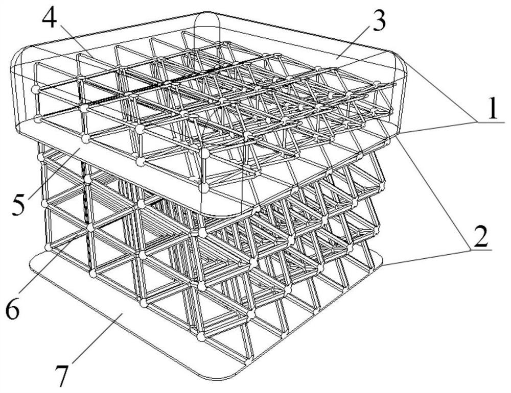
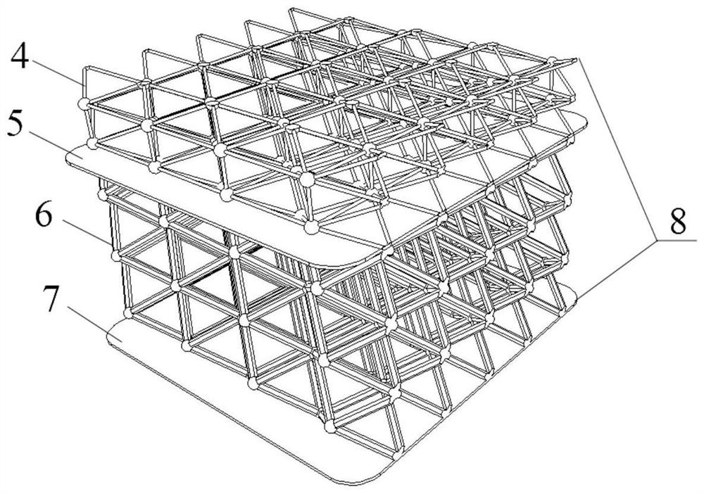
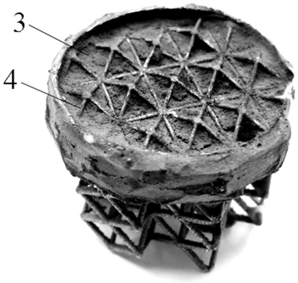
[0028] see Figures 1 to 3 , a metal lattice reinforced ablative material sandwich panel structure, comprising an integrally formed metal lattice sandwich panel skeleton 8 and internal filling material; the integrally formed metal lattice sandwich panel skeleton 8 includes a first metal lattice core 4 and the connecting rod between the lattice core, the second metal lattice core 6 and the connecting rod between the lattice cor...


PUM


Abstract

The invention discloses a metal dot matrix reinforced ablative material sandwich plate structure which is characterized in that an integrally formed metal dot matrix sandwich plate is used as a framework, a force bearing structure and a heat-proof structure are organically combined, and a connecting interface between functional structures is eliminated; the force bearing structure adopts a metal dot matrix sandwich plate structure form, and provides more efficient mechanical properties than a traditional sandwich structure; a base body of the heat-proof structure is made of a low-density ablation-resistant high polymer material, and a reinforcing body is made of a metal dot matrix core, so that the mass ablation rate of the heat-proof structure can be effectively reduced; and the phase-change material is packed in the sandwich plate of the bearing structure, so that local high temperature caused by thermal short circuit of the metal dot matrix can be further relieved. On the premise of the same bearing capacity, a lighter structural form can be provided, and the risk of interface connection failure of the heat-proof structure and the force bearing structure under the pneumatic thermal scouring condition can be eliminated.

Description

technical field [0001] The invention belongs to the field of thermal protection systems for aircraft structures, and in particular relates to a metal lattice reinforced ablation material sandwich plate structure suitable for reentry aircraft. Background technique [0002] In the future, space shuttles and interstellar transportation activities of spacecraft will become increasingly frequent, and the demand for a lighter and more reliable thermal protection system (Thermal Protection System, TPS) will be more urgent, which has aroused widespread interest in the fields of scientific theory and aerospace engineering. Ongoing attention. [0003] After the 1960s, the heat-proof structure of the re-entry vehicle gradually adopted a sandwich structure with both heat-proof and load-bearing properties, and low-density ablative materials gradually became the most commonly used heat-proof method, widely used in high specific enthalpy, Thermal barrier environmental protection with low ...

Claims


Application Information

Patent Timeline
IPC IPC(8): B32B15/20B32B15/00B32B15/04B64G1/58
CPCB32B15/20B32B15/00B32B15/04B64G1/58B32B2307/718B32B2307/3065Y02P10/25
Inventor 胡励林仁邦冀宾闫世宇黄强陈鸣亮张醒
Owner SHANGHAI AEROSPACE SYST ENG INST
Learn More