Heat supply system of gas boiler room and energy utilization method

A technology for heating systems and boiler rooms, applied in heating systems, heating methods, household heating, etc., can solve the problems of insufficient resource conservation and civilization, transmission efficiency, environmental pollution that cannot meet energy demand, and energy utilization in gas-fired boiler rooms Single and extensive methods, etc., to achieve the effect of improving comprehensive energy utilization efficiency, increasing annual utilization rate, and saving gas consumption

Active Publication Date: 2021-11-05
JINAN MUNICIPAL ENG DESIGN & RES INSITITUTE GRP
View PDF10 Cites 2 Cited by
  • Summary
  • Abstract
  • Description
  • Claims
  • Application Information

AI Technical Summary

Problems solved by technology

[0002] The traditional gas-fired boiler room only relies on gas combustion to generate energy in terms of centralized functions, which can no longer meet my country's energy demand in terms of transmission efficiency and environmental pollution.
The energy utilization mode of the gas boiler room is single and extensive, and the degree of resource conservation and civilization is not enough

Method used


Image

  • Heat supply system of gas boiler room and energy utilization method
  • Heat supply system of gas boiler room and energy utilization method

Examples


Embodiment 1

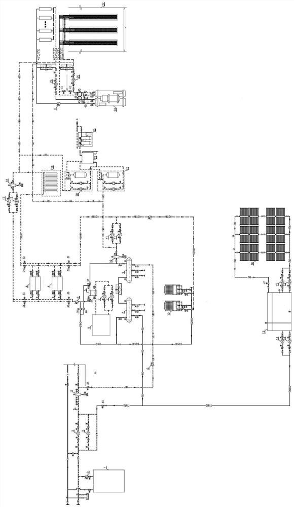
[0047] Such as Figure 1-2 As shown, the present invention discloses a heating system for a gas-fired boiler room. The system is a heating system that realizes "multi-energy complementarity" for a gas-fired boiler room. The connection of water tank and water collector; the connection of air source heat pump system, ground source heat pump system and cross-season energy storage water ring system are connected in parallel.

[0048] The boiler hot water system includes a boiler, the water outlet of the boiler is connected to the water supply pipeline; the water inlet of the boiler is connected to the return water pipeline. A heating system circulating water pump 2 and a heating system decontamination device 3 are arranged on the return water pipeline. The return water pipeline is respectively connected with the solar hot water supply pipe and the heating return water pipe. The design temperature of the gas boiler 1 hot water system is 40 / 110°C, and the quantity-quality adjustme...

Embodiment 2

[0061] In the second aspect, the present disclosure also relates to an energy utilization method, based on a heating system of a gas boiler room 1 of the present disclosure, specifically as follows:

[0062] During central heating in winter, when the outlet temperature of the solar collector 16 reaches the set temperature of 60°C, the seventeenth electric valve 47 is opened and the solar hot water heat storage circulating water pump 15 is chained to start the high temperature water pressure in the solar collector 16. into the solar hot water storage tank 13; when the outlet temperature of the solar collector 16 reaches the set temperature of 45°C, the solar hot water heat storage circulating water pump 15 is closed, and the seventeenth electric valve 47 is closed; the above process is repeated, The water level in the solar hot water storage tank 13 gradually rises, and when the water level in the hot water storage tank reaches 100%, the seventeenth electric valve 47 and the sol...


PUM


Abstract

The invention relates to the technical field of heat supply, in particular to a heat supply system of a gas boiler room and an energy utilization method. The invention discloses the heat supply system of the gas boiler room. The heat supply system of the gas boiler room comprises a boiler hot water system which is respectively connected with a solar heat collector and an air source heat pump system; the air source heat pump system is connected with a ground source heat pump system; and a cross-seasonal energy storage water ring system is connected with the ground source heat pump system. When the solar radiation intensity is low, air energy and geothermal energy serve as auxiliary devices to provide heat, the return water temperature of a gas-fired boiler is increased, the gas consumption is reduced, and multi-energy complementation is achieved.

Description

technical field [0001] The present disclosure relates to the technical field of heat supply, in particular to a heat supply system and an energy utilization method for a gas boiler room. Background technique [0002] The traditional gas-fired boiler room only relies on gas combustion to generate energy in terms of centralized functions, which can no longer meet my country's energy demand in terms of transmission efficiency and environmental pollution. The energy utilization mode of the gas-fired boiler room is single and extensive, and the degree of resource conservation and civilization is not enough. Due to the characteristics of my country's energy resources of "auxiliary coal, poor oil, and little gas", the development of solar energy, ground source heat pumps, and cross-seasonal energy storage complementary heating systems is more in line with my country's national conditions. [0003] "Multi-energy utilization" adapts measures to local conditions and according to the ...

Claims


Application Information

Patent Timeline
Patent Type & Authority Applications(China)
IPC IPC(8): F24D11/02F24D19/10
CPCF24D11/0221F24D19/1045Y02B10/20Y02B10/40Y02B10/70
Inventor 王茂盛杨敏华刘倩曹东辉蔡振兴王磊石风鹤
Owner JINAN MUNICIPAL ENG DESIGN & RES INSITITUTE GRP
Why Eureka
Try Eureka