Airborne conformal bearing antenna

A technology of antenna and microstrip antenna, which is applied in the direction of antenna, antenna support/mounting device, antenna grounding switch structure connection, etc., which can solve the problem of lack of ability to integrate back-end components, limited antenna aperture, and high local stiffness of the skin to achieve excellent structural rigidity, increase power, and increase caliber

Active Publication Date: 2021-11-05
CHINA ELECTRONIC TECH GRP CORP NO 38 RES INST
View PDF10 Cites 1 Cited by
  • Summary
  • Abstract
  • Description
  • Claims
  • Application Information

AI Technical Summary

Problems solved by technology

However, in the technical solution of the above-mentioned patent, in order to install the connector, part of the foam sandwich is replaced by an aluminum alloy transition plate of equal thickness, resulting in excessive local stiffness of the skin, so the skin antenna is suitable for applications with small loads. area, does not have the ability to integrate back-end components, and the antenna aperture is also limited

Method used


Image

  • Airborne conformal bearing antenna
  • Airborne conformal bearing antenna

Examples


Embodiment Construction

[0029] In order to make the purpose, technical solutions and advantages of the embodiments of the present invention clearer, the technical solutions in the embodiments of the present invention will be clearly and completely described below in conjunction with the embodiments of the present invention. Obviously, the described embodiments are part of the present invention Examples, not all examples. Based on the embodiments of the present invention, all other embodiments obtained by those skilled in the art without creative efforts fall within the protection scope of the present invention.

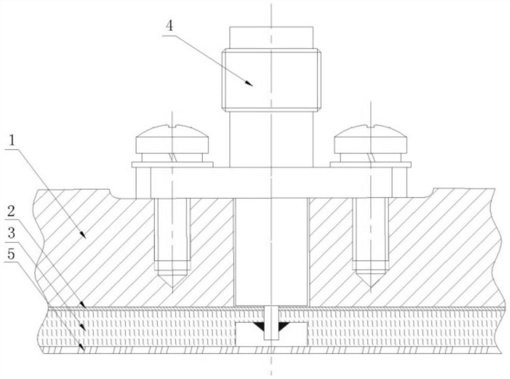
[0030] This embodiment proposes an X-band airborne conformal load-carrying antenna capable of bearing aerodynamic loads and participating in airframe load transfer. refer to figure 1 , figure 1 A schematic cross-sectional structure diagram of an airborne conformal load-carrying antenna provided by an embodiment of the present invention, the airborne conformal load-bearing antenna includes ...


PUM


Abstract

An airborne conformal bearing antenna of the present invention comprises a reflecting plate, a microstrip antenna, a radio frequency connector and a skin, wherein the reflecting plate is of a bearing structure, and the inner side of the reflecting plate is provided with a rear-end device and a fixing interface of the radio frequency connector; the microstrip antenna is fixed at the outer side of the reflecting plate; the skin has a wave-transparent function and is laid at the outer side of the microstrip antenna, and the appearance of the skin is consistent with the aerodynamic appearance of an airplane. After integral forming, the mechanical connection between the conformal antenna and an aircraft structure is realized through the installation holes in the reflecting plate. The airborne conformal bearing antenna has excellent structural rigidity, and the aperture of the airborne conformal antenna can be remarkably improved; the antenna has the capability of hanging a rear-end active device, reduces the loss between the rear-end active device and the antenna, and further improves the power of a detection system.

Description

technical field [0001] The invention relates to the technical field of antenna structures, in particular to an airborne conformal bearing antenna. Background technique [0002] The conformal antenna refers to the array antenna attached to the surface of the carrier and bonded to the carrier, that is, the array antenna needs to be conformally installed on a fixed-shaped surface to form a non-planar conformal antenna array. [0003] Compared with planar antennas, conformal antennas have the following advantages: [0004] 1) Improve radar wide-angle scanning performance; [0005] 2) Eliminate or reduce the aiming error caused by the radome; [0006] 3) The antenna can be conformally placed at any position of the carrier to achieve full spatial coverage of the pattern. [0007] Airborne radar has the advantages of long detection distance and long warning time. Aircraft is currently the most widely used carrier for conformal antennas, because conformal antennas can eliminate t...

Claims


Application Information

Patent Timeline
Patent Type & Authority Applications(China)
IPC IPC(8): H01Q1/12H01Q1/28H01Q1/42H01Q1/50H01Q19/10
CPCH01Q1/285H01Q1/50H01Q19/10H01Q1/12H01Q1/42Y02T50/40
Inventor 杨竣博郭琳吴斌徐振华赵丹陈路加闫修陈声麒王德才贺旭东黄小庆陶海峰
Owner CHINA ELECTRONIC TECH GRP CORP NO 38 RES INST
Why Eureka
Try Eureka