Cutting device for machining
A cutting device and machining technology, applied in shearing devices, metal processing equipment, accessories of shearing machines, etc., can solve the problems of easy accumulation of waste at the incision, unevenness at the exit of the workpiece, deviation of the cutting position, etc. Achieve the effect of improving the cutting effect, reducing the probability of scrapping, and reducing deformation
- Summary
- Abstract
- Description
- Claims
- Application Information
AI Technical Summary
Problems solved by technology
Method used
Image

Examples
Embodiment 1
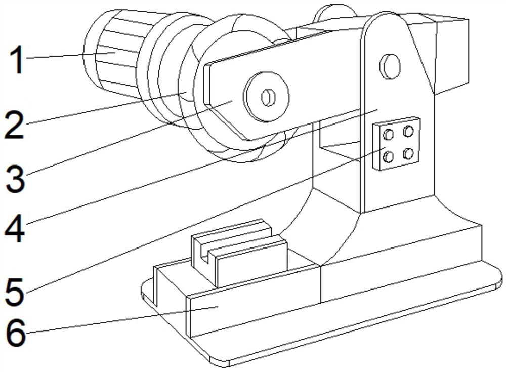
[0035] see Figure 1-2, the present invention provides a technical solution: a cutting device for mechanical processing, including a force arm 4, a fixing device 6 is fixedly connected to the bottom of the force arm 4, a controller 5 is fixedly connected to the front middle part of the force arm 4, and the force arm 4 There is a bracket 3 on the top of the inner wall on both sides of the bracket 3, and a motor 1 is installed on the back of the bracket 3 away from the force arm 4. The output shaft of the motor 1 runs through the bracket 3 and extends to the inside of the bracket 3, and the inner walls on both sides of the bracket 3 are close to the position of the motor. A cutting knife 2 is provided.
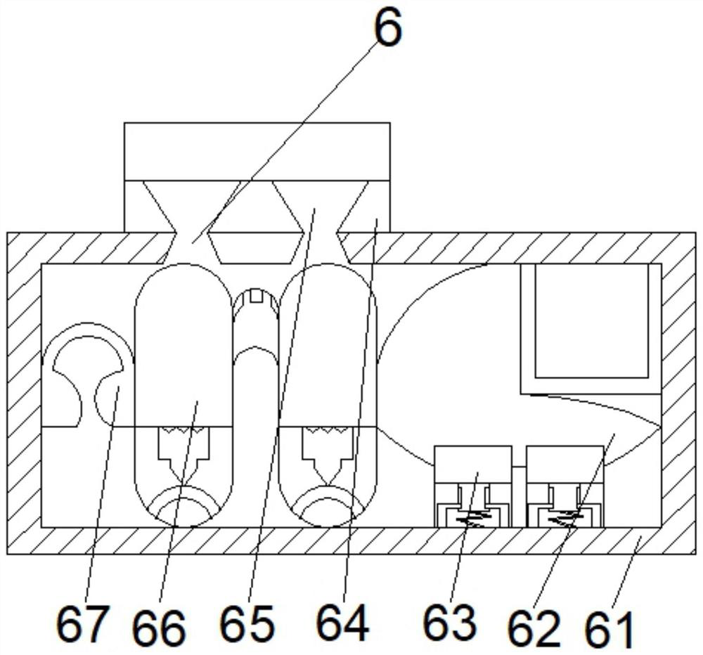
[0036] Wherein, the fixing device 6 includes a base 61, the top left side of the base 61 is fixedly connected with a fixer 64, the bottom of the inner cavity of the fixer 64 is provided with a tapered hole 65, and the position of the bracket at the bottom of the inner cavity of ...
Embodiment 2
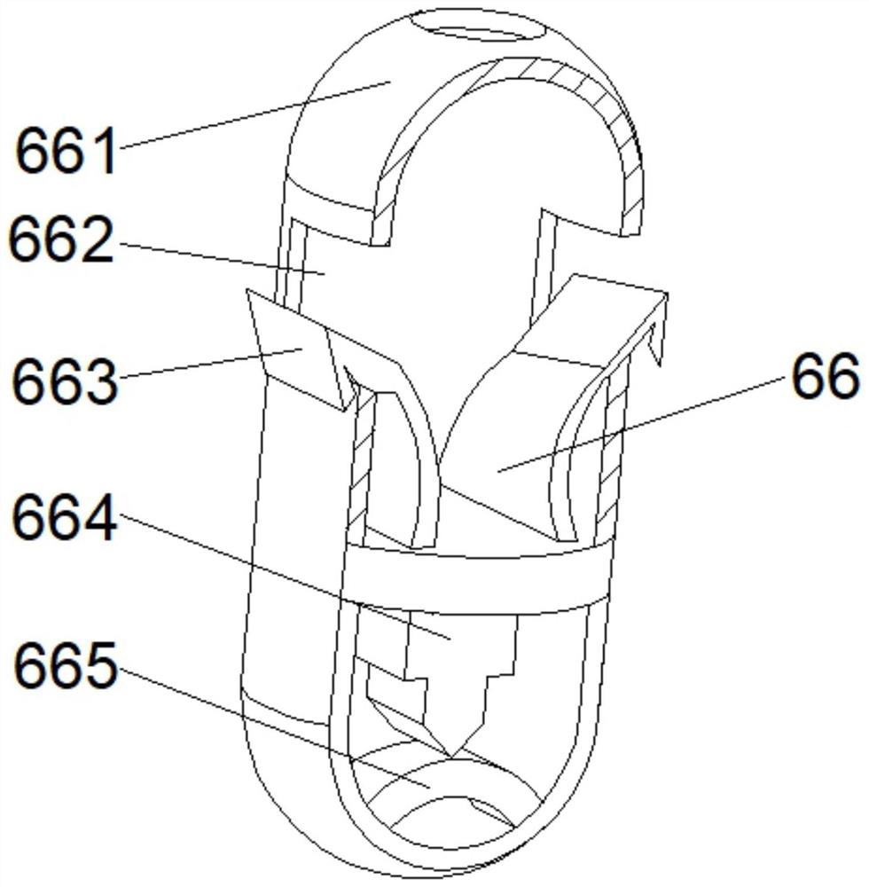
[0039] see Figure 1-4 On the basis of Embodiment 1, the present invention provides a technical solution: the collection mechanism 66 includes a housing 661, the bottom of the inner cavity of the housing 661 is fixedly connected with a bottom plate 665, and a blocking mechanism is provided at the middle position of the top of the bottom plate 665 664, side plates 663 are fixedly connected to both sides of the top of the blocking mechanism 664, a flow groove 662 is opened in the middle of the outer walls of both sides of the casing 661, and the position of the side plate 663 away from the blocking mechanism 664 runs through the flow groove 662 and extends to the outside of the flow groove 662 .
[0040] Wherein, the blocking mechanism 664 includes a blocking block d1, a positioning block d2 is fixedly connected to both sides of the top of the inner cavity of the blocking block d1, and a reset rod d3 is fixedly connected to the bottom of the outer walls of both sides of the posi...
Embodiment 3
[0043] see Figure 1-7 , on the basis of Embodiment 1 and Embodiment 2, the present invention provides a technical solution: the auxiliary mechanism d6 includes an elastic block d61, and the middle part of the inner wall on both sides of the elastic block d61 is fixedly connected with a contact strip d62, and the contact strip d62 is connected with the elastic block A blocking plate d63 is fixedly connected between d61, a middle solid block d64 is fixedly connected to the top of the elastic block d61, and a transition block d65 is arranged on the top of the outer walls of both sides of the middle solid block d64.
[0044] Wherein, the transition block d65 includes a bonding block t1, the contact increasing block t3 is fixedly connected to the top of the bonding block t1, and the bottom left side of the contact increasing block t3 is fixedly connected to the limiting rod t2.
[0045] Wherein, the contact increasing block t3 includes a top plate t32, the bottom of the top plate ...
PUM
 Abstract
Description
Claims
Application Information
 - R&D
- Intellectual Property
- Life Sciences
- Materials
- Tech Scout
- Unparalleled Data Quality
- Higher Quality Content
- 60% Fewer Hallucinations
Browse by: Latest US Patents, China's latest patents, Technical Efficacy Thesaurus, Application Domain, Technology Topic, Popular Technical Reports.
© 2025 PatSnap. All rights reserved.Legal|Privacy policy|Modern Slavery Act Transparency Statement|Sitemap|About US| Contact US: help@patsnap.com