Eureka AIR delivers breakthrough ideas for toughest innovation challenges, trusted by R&D personnel around the world.

A kind of cylindrical grinding process of wafer dicing blade

A technology for cutting blades and wafers, which is applied in the direction of grinding workpiece holders, manufacturing tools, grinding drive devices, etc., can solve problems such as edge fracture and edge stress damage of annular blades, and achieve improved sharpness, accuracy, The effect of improving stability

Active Publication Date: 2021-12-28
南通伟腾半导体科技有限公司
View PDF3 Cites 0 Cited by
  • Summary
  • Abstract
  • Description
  • Claims
  • Application Information

AI Technical Summary

Problems solved by technology

[0003] At present, when processing wafers, wafer dicing blades are mainly used to process and cut wafers. The production process of wafer dicing blades generally needs to go through steps such as pretreatment, composite deposition, semi-finished product inspection, and outer circle grinding. When grinding, the edge of the ring blade is polished. This process is directly related to the final sharpness of the wafer cutting blade. During the grinding process, the grinding wheel is generally used to directly act on the edge of the ring blade to completely grind the edge of the ring blade. However, in the actual grinding process, the grinding of the grinding wheel can easily lead to stress damage inside the edge of the ring blade, which makes the edge of the ring blade very fragile, and often breaks when the wafer is subsequently cut phenomenon, the grinding position of the grinding wheel on the annular blade is particularly important, which is directly related to the pass rate and sharpness of the final shaped blade

Method used


Image

  • A kind of cylindrical grinding process of wafer dicing blade
  • A kind of cylindrical grinding process of wafer dicing blade

Examples


specific Embodiment approach

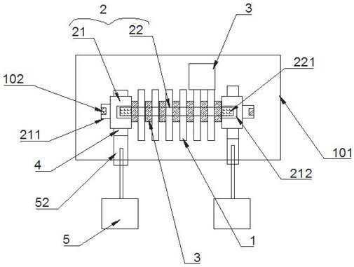
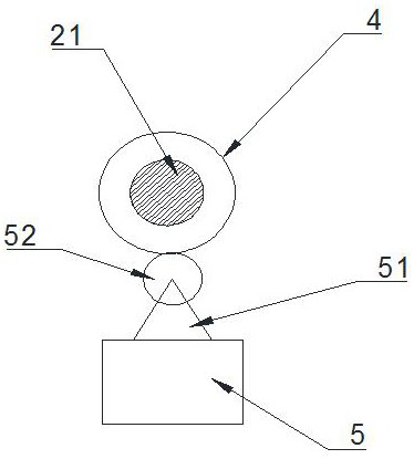
[0022] like Figure 1 to Figure 2 A specific embodiment of the present invention specifically includes the following steps:

[0023] S1. Install several annular blades 1 concentrically on the grinding tool 2, and a protective block 3 is separated between two adjacent annular blades 1;

[0024] S2, rotating and installing the grinding tool 2 on the machine tool 101, during installation, the machining center line of the machine tool 101 coincides with the center line of the grinding tool 2;

[0025] S3, the rotating grinding tool 2 is approached to the rotating emery wheel 6, the rotation direction of the grinding wheel 6 is opposite to that of the grinding tool 2, and the grinding wheel 6 grinds the edge of the annular blade 1;

[0026] In the step S3, an industrial camera is used to find defects on the end face of the annular blade 1 at any time, and the feed rate and grinding position of the grinding wheel 6 are controlled according to the defects of the annular blade 1 .

...


PUM


Abstract

The invention discloses an outer circle grinding process of a wafer cutting blade, which specifically comprises the following steps: installing a plurality of annular blades concentrically on a grinding tool, and separating a protective block between two adjacent annular blades; The tooling is rotated and installed on the machine tool. When installing, the machining center line of the machine tool coincides with the center line of the grinding tooling. The rotating grinding tooling is placed close to the rotating grinding wheel. The rotation direction of the grinding wheel is opposite to that of the grinding tooling. The edge is polished, and in the step S3, an industrial camera is used to find defects on the end face of the ring blade at any time, and the feed rate and the grinding position of the grinding wheel are controlled according to the defects of the ring blade. The present invention improves the accuracy of the grinding wheel to the grinding position of the ring blade. sex.

Description

Technical field: [0001] The invention relates to the technical field of production of a wafer cutting blade, in particular to an outer circle grinding process of a wafer cutting blade. Background technique: [0002] Wafer dicing is an essential process in the semiconductor chip manufacturing process. It is a post-process in wafer manufacturing. Its working principle is to divide the positive wafer of the chip into a single chip according to the size of the chip. Therefore, in this process, wafer cutting blades are generally used for cutting, and the sharpness of the wafer cutting blades is particularly important. [0003] At present, when processing wafers, wafer dicing blades are mainly used to process and cut wafers. The production process of wafer dicing blades generally needs to go through steps such as pretreatment, composite deposition, semi-finished product inspection, and outer circle grinding. When grinding, the edge of the ring blade is polished. This process is d...

Claims


Application Information

Patent Timeline
Patent Type & Authority Patents(China)
IPC IPC(8): B24B3/36B24B41/06B24B47/20
CPCB24B3/363B24B41/067B24B47/20
Inventor 赵正东朱恺华焦旭东王百强赵明杰
Owner 南通伟腾半导体科技有限公司
Why Eureka
Eureka Blog
Learn More