Optical filter laser cutting method

A laser cutting and filter technology, applied in glass cutting devices, manufacturing tools, glass manufacturing equipment, etc., can solve the problems of large, usually 30 microns or even 50 microns, and the cutting effect is not ideal, and achieve small divergence angles, Reduced damage effect, high depth of focus effect

Pending Publication Date: 2021-11-09
苏州捷兴激光设备有限公司
View PDF5 Cites 1 Cited by
  • Summary
  • Abstract
  • Description
  • Claims
  • Application Information

AI Technical Summary

Problems solved by technology

The performance of the laser manufacturing industry is inseparable from the prosperity of the overall industry. The cutting damage

Method used


Image

  • Optical filter laser cutting method
  • Optical filter laser cutting method

Examples


Embodiment Construction

[0022] In order to deepen the understanding of the present invention, the present invention will be described in detail below with reference to the accompanying drawings and examples, and the present invention is intended to be construed as limiting the scope of the invention.

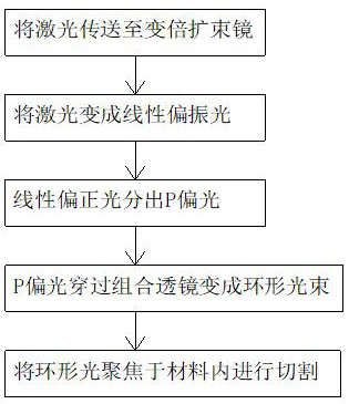
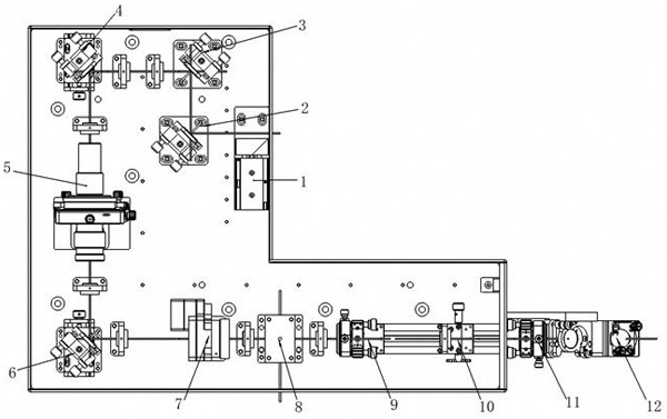
[0023] A filter laser cutting method, the practical cutting equipment used in this example, figure 2 As shown, the laser is adjusted from the light source, and the output power and the spot shape conform to the annular beam of the processed, and then the core beam is focused on the processed material, and the following steps are specifically including the following steps:

[0024] S1, the Gaussian light output by the green laser is transmitted to the first mirror 2 by the first optical gate 1, and then passes through the second mirror 3, the third mirror 4 is transferred to the variational expansion mirror 5; The mirror changes the propagation path of the light to ensure that the optical path stroke is wit...


PUM


Abstract

The invention relates to the technical field of optical filter cutting, and discloses an optical filter laser cutting method which comprises the following steps: S1, Gaussian light outputted by a green laser is transmitted to a zoom beam expander through a plurality of reflectors; s2, the laser passing through the zoom beam expander is transmitted to a 1/2 crystal wavelength plate through a reflector, so that the laser is changed into linear polarized light with an adjustable polarization direction; s3, the linear polarized light is divided into S polarized light and P polarized light after passing through a polarized light cube spectroscope; s4, the P polarized light is transmitted to a combined lens to form an annular light beam of which the energy density is gradually reduced from inside to outside; and S5, the annular light beam is transmitted to a focusing mirror through a reflecting mirror, the annular light beam is focused in the material, the focusing mirror is driven to move through a servo control system, and the material is cut. The laser is transmitted to a to-be-processed optical filter material after passing through a plurality of groups of reflectors and the combined lens, and the cutting damage influence is reduced to be within 5 microns by controlling the laser power and the light spot shape.

Description

Technical field [0001] The present invention relates to a cutting method, and more particularly to a filter laser cutting method. Background technique [0002] In recent years, the mobile phone industry has developed rapidly. With the popularity of high-end mobile phones in 4 photos, 8-fitting high-end mobile phones, the demand in the camera module grows faster, and the current large chip vendors such as five-party photoelectric, crystal optoelectronics, Star Wave Optics, etc. are all expanded to meet the growing consumer demand. The laser cut is currently the main cutting method, and the high power density laser beam is used to illuminate the cut material so that the material is quickly heated to the vaporization temperature, evaporated to form a hole, and the hole continuously forms a width of the width as the light beam moves with the light beam , Complete the cutting of materials. The performance of the laser manufacturing industry is inseparable from the overall industries. ...

Claims


Application Information

Patent Timeline
IPC IPC(8): C03B33/08
CPCC03B33/082
Inventor 邵西河
Owner 苏州捷兴激光设备有限公司
Why Eureka
Try Eureka