
Water-cooled slag discharging device and method for realizing water circulation

A water circulation, water-cooled technology, applied in laser welding equipment, welding/welding/cutting items, manufacturing tools, etc., can solve the problem of fast slag discharge, rising water temperature, and the inability of the slag discharge trolley to be pulled out from the bottom of the machine tool when it passes through thermal deformation and other problems to achieve the effect of ensuring normal slag discharge

Active Publication Date: 2021-11-12
PENTA CHUTIAN LASER (WENZHOU) CO LTD
View PDF7 Cites 0 Cited by
  • Summary
  • Abstract
  • Description
  • Claims
  • Application Information

AI Technical Summary

Problems solved by technology

However, because the slag discharge trolley at the bottom of the laser cutting machine is under the laser cutting area, the received laser energy density is high, and the frequency of receiving laser energy is high, so it often happens that the slag discharge trolley cannot be pulled out from the bottom of the machine tool due to thermal deformation caused by the laser. problems, resulting in the inability to achieve faster slag discharge during slag discharge, and the common water-cooled slag discharge method, the water temperature will continue to rise under the action of the laser, so that the heat absorption efficiency of the water to the laser is reduced, which is still very Easy to cause damage to the slag discharge device

Method used


Image

  • Water-cooled slag discharging device and method for realizing water circulation
  • Water-cooled slag discharging device and method for realizing water circulation
  • Water-cooled slag discharging device and method for realizing water circulation

Examples


Embodiment 1

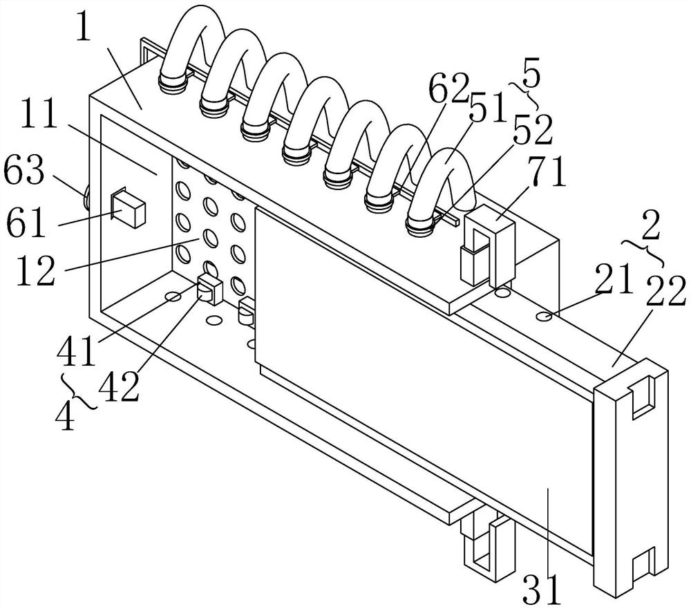
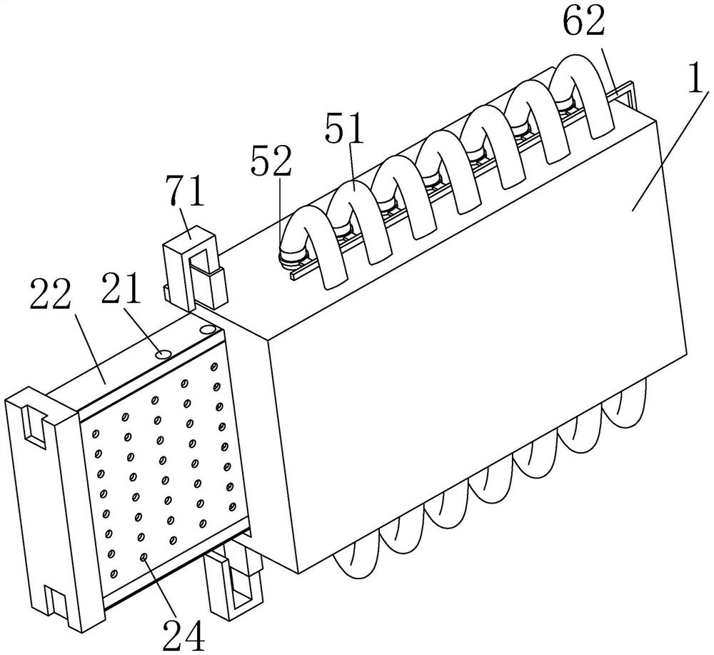
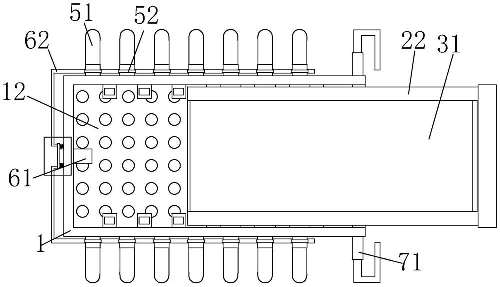
[0038] Such as Figure 1-Figure 6 As shown, a water-cooled slag discharge device that realizes water circulation includes a box body 1 and a bearing assembly 2. The box body 1 is provided with a sliding chamber 11 for storing and moving the loading assembly 2. The loading assembly 2 can be moved along the length direction of the box body 1. Disassemble and connect in the sliding cavity 11;

[0039] The bearing assembly 2 includes a support plate 22, on which a refractory plate 31 for resisting laser light and collecting residue is connected, and a water cooling cavity 23 for storing water is provided between the support plate 22 and the refractory plate 31, and the water cooling cavity 23 is along the refractory The board 31 is set in the width direction and extends along the length direction of the refractory board 31. The box body 1 is also provided with a water storage chamber 14 for storing excess water in the water cooling chamber 23. The water storage chamber 14 is locat...

Embodiment approach

[0071] Such as Figure 6-Figure 10 As shown, based on the above-mentioned water-cooled slagging device for realizing water circulation of the present invention, the present invention also provides another embodiment of the device, including:

[0072] Divide several water pipes 51 into two parts according to the sliding direction of the support plate 22 in the sliding chamber 11, and a part of the water pipes 51 close to the sliding terminal of the support plate 22 is still connected by the connecting rod 62 to control the baffle plate 52. One end of a part of the baffle plate 52 at the beginning of the sliding of the support plate 22 is connected with a moving rod 84, that is, the water pipe 51 near the beginning of the sliding of the supporting plate 22, and the moving rod 84 controls the baffle 52 to realize communication.

[0073] Both sides of the support plate 22 in the width direction are connected with two racks 81, and the two racks 81 are located in the middle of the ...


PUM


Abstract

The invention relates to a water-cooled slag discharging device for realizing water circulation. The water-cooled slag discharging device comprises a box body and a bearing assembly, wherein a sliding cavity for storing and moving the bearing assembly is formed in the box body; the bearing assembly is detachably connected into the sliding cavity; the bearing assembly comprises a supporting plate; a refractory plate for resisting laser and collecting residues is connected onto the supporting plate; a water-cooled cavity for storing water is formed between the supporting plate and the refractory plate; the water-cooled cavity is formed along the width direction of the refractory plate and extends along the length direction of the refractory plate; a water storage cavity for storing excessive water of the water-cooled cavity is formed in the box body; the water storage cavity is positioned on one side, far away from the bearing assembly, of the sliding cavity; and a water circulation assembly for recycling cooling water is connected between the water storage cavity and the water-cooled cavity. According to the water-cooled slag discharging device disclosed by the invention, laser rays are subjected to heat reduction and ablation by the refractory plate, the water-cooled cavity and the water storage cavity, so that the laser rays are prevented from deforming the body of a slag discharging trolley, and normal slag discharging of the slag discharging device is ensured.

Description

【Technical field】 [0001] The invention relates to laser cutting machine equipment, in particular to a water-cooled slag discharge device and method for realizing water circulation. 【Background technique】 [0002] At present, with the continuous improvement of the cutting capacity of high-power laser cutting machines, the thickness of cutting metal materials is also gradually increasing. In order to avoid cutting the laser cutting machine when cutting metal sheets, laser cutting manufacturers usually use refractory mud or graphite to coat Laser cutting machine interior to prevent laser burns. However, because the slag discharge trolley at the bottom of the laser cutting machine is right under the laser cutting area, the received laser energy density is high, and the frequency of receiving laser energy is high, so it often happens that the slag discharge trolley cannot be pulled out from the bottom of the machine tool due to thermal deformation caused by the laser. problems, ...

Claims


Application Information

Patent Timeline
Patent Type & Authority Applications(China)
IPC IPC(8): B23K26/70B23K26/38B23K26/402
CPCB23K26/702B23K26/38B23K26/402B23K2103/50
Inventor 蔡亮付兴威吴欣曹宇李正吴淑玲谌维鹏
Owner PENTA CHUTIAN LASER (WENZHOU) CO LTD
Learn More