

Workpiece clamping and fixing device
A technology for fixing devices and workpiece clamps, which is applied in the directions of positioning devices, clamping devices, clamping, etc., can solve the problems of high cost, prolonged downtime of processing machine tools, and cumbersome refitting, so as to reduce the cost of transformation, facilitate maintenance and upgrading, and widely fitness effect
- Summary
- Abstract
- Description
- Claims
- Application Information
AI Technical Summary
Problems solved by technology
Method used
Image

Examples
Embodiment 1
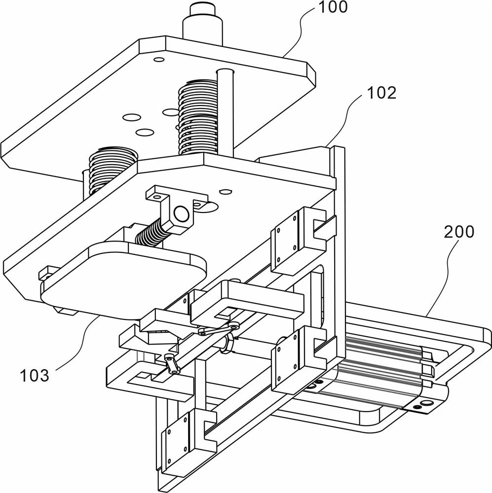
[0030] refer to figure 1 and 2 , which is the first embodiment of the present invention, provides a workpiece clamping and fixing device, which includes a moving assembly 100 and a fixing assembly 200, wherein the moving assembly 100, including a moving frame 101, is arranged on the moving frame 101 The cushioning member 102 and the positioning member 103; the fixing assembly 200, which is arranged on the moving frame 101, includes a fixing frame 201, a cylinder 202 arranged in the fixing frame 201, a connecting rod 203 connected with the cylinder 202, The gripper 204 is movably connected with the connecting rod 203 .
[0031] Wherein, the moving assembly 100 is used to move the fixing device so that it can float up and down, the moving frame 101 carries the entire fixing device, and the moving frame 101 also carries the buffer piece 102 and the positioning piece 103; Down force, the positioning member 103 is used to contact the workpiece for the first time and provide the p...
Embodiment 2
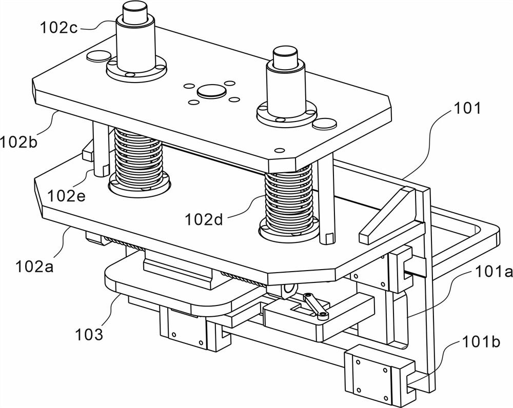
[0033] refer to image 3 , is the second embodiment of the present invention, which differs from the first embodiment in that: a connecting hole 101a is opened in the center of the mobile frame 101, and several counterweights 101b are arranged on the side walls. The buffer member 102 includes a fixed plate 102a and a movable plate 102b. The fixed plate 102a is fixedly connected with the mobile frame 101 and vertically arranged on the side wall of the mobile frame 101. The movable plate 102b is arranged parallel to the fixed plate 102a.
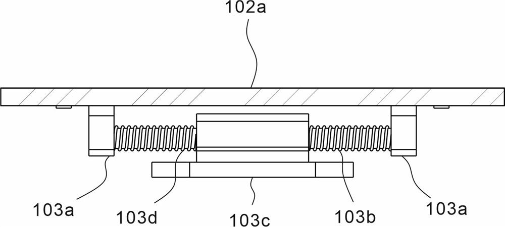
[0034] A sliding bar 102c is arranged symmetrically between the fixed plate 102a and the movable plate 102b. The fixed plate 102a is fixedly connected to the sliding bar 102c, and the movable plate 102b is slidably connected to the sliding bar 102c. Between the plate 102a and the movable plate 102b, and between the fixed plate 102a and the movable plate 102b, several limit rods 102e are also arranged. Positioning piece 103 is arranged on the ...
Embodiment 3
[0040] refer to Figure 4 , 5 And 6, is the third embodiment of the present invention, and this embodiment is different from the second embodiment in that: the fixed frame 201 passes through the connecting hole 101a, and vertical rods 201a are symmetrically arranged in the connecting hole 101a, and the fixed frame 201 and the The vertical bar 201a is fixedly connected, and the fixing frame 201 is generally rectangular, with an opening on one side, and a concave frame 201b at both ends of the opening. The air cylinder 202 is arranged inside the fixed frame 201, and its tail end is fixedly connected with the side of the fixed frame 201 away from the concave frame 201b, and the telescopic end passes through the connecting hole 101a.
[0041] The connecting rod 203 is fixedly connected to the telescopic end of the cylinder 202, and its length is greater than the distance between the two concave frames 201b; the top of the connecting rod 203 is symmetrically provided with a first ...
PUM
 Abstract
Description
Claims
Application Information