
Multi-mode hybrid drive system

A technology of hybrid power and drive system, which is applied to the layout of multiple prime movers of power plants, pneumatic power plants, and general-purpose power plants. It can solve problems such as poor layout, unstable battery life, and long charging time. Achieve good power performance and driving performance, improve energy recovery efficiency, and improve fuel economy

Pending Publication Date: 2021-11-12
CHONGQING TSINGSHAN IND
View PDF0 Cites 0 Cited by
  • Summary
  • Abstract
  • Description
  • Claims
  • Application Information

AI Technical Summary

Problems solved by technology

However, pure electric vehicles in new energy vehicles have problems that are difficult to solve in the short term, such as high vehicle cost, long charging time, and unstable battery life. It has the advantages of both electric vehicles and pure electric vehicles, and has a variety of efficient driving modes, which can be driven by the engine and the first motor at the same time, and can also be driven by the engine or the first motor alone
[0003] At present, hybrid vehicles usually use one engine and one motor to provide driving force, with few gear options, poor adaptability, inability to start the engine while driving, poor fuel-saving effect, and even the power is easily interrupted when changing gears. The driving experience is not good, and it is easy to cause accidents
There are also some hybrid vehicles that use one engine and two motors, and the two motors are arranged in parallel, which requires a large space and poor layout

Method used


Image

  • Multi-mode hybrid drive system
  • Multi-mode hybrid drive system
  • Multi-mode hybrid drive system

Examples


Embodiment 1

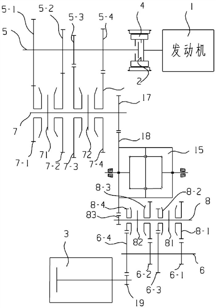
[0026] Such as figure 1 , the first transmission assembly mostly includes a first driving gear 5-1, a second driving gear 5-2, a third driving gear 5-3, a fourth driving gear 5-4, a first driven gear 7-1, a second driving gear Driven gear 7-2, the 3rd driven gear 7-3, the 4th driven gear 7-4, the first synchronizer 71, the second synchronizer 72, the first transmission gear 17, wherein, the first driving gear 5 -1, the second driving gear 5-2, the third driving gear 5-3, the fourth driving gear 5-4 are respectively fixed with the input shaft 5, the first driven gear 7-1, the second driven gear 7-2 , the third driven gear 7-3, and the fourth driven gear 7-4 are respectively vacantly sleeved on the intermediate shaft 7.

[0027] The first driving gear 5-1 meshes with the first driven gear 7-1 to form the first gear pair, and the second driving gear 5-2 meshes with the second driven gear 7-2 to form the second gear pair. The third driving gear 5-3 meshes with the third driven g...

Embodiment 2

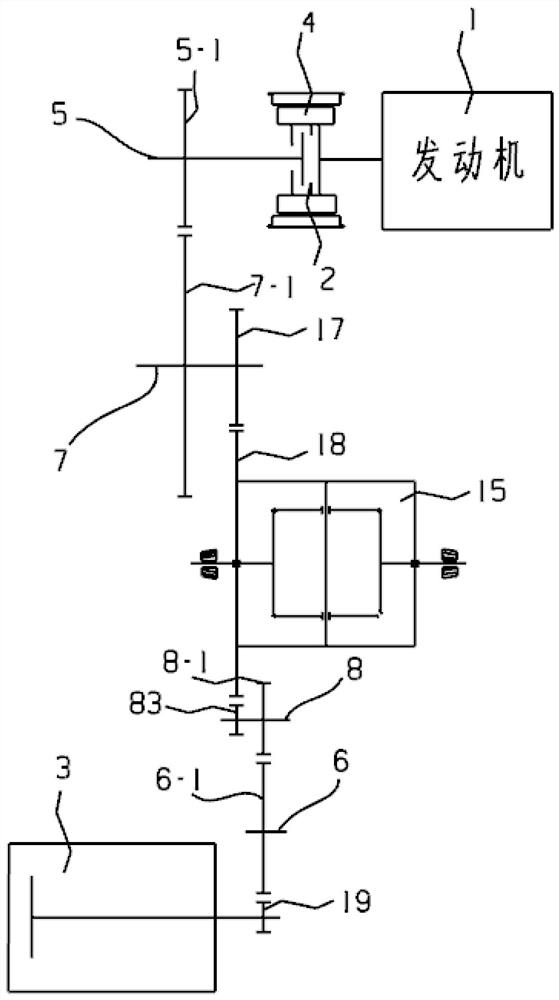
[0033] Such as figure 2 , the first transmission assembly mostly includes a first driving gear 5-1, a first driven gear 7-1, and a first transmission gear 17, wherein the first driving gear 5-1 is fixed to the input shaft 5, and the first driven gear 7-1 empty set on the intermediate shaft 7. The first driving gear 5-1 meshes with the first driven gear 7-1 to form the first gear pair, the first transmission gear 17 is fixed to the intermediate shaft 7, and the differential speed between the first transmission gear 17 and the differential 15 The gear input gear 18 meshes.

[0034] The second transmission assembly comprises input gear 19, first input gear 6-1, first intermediate gear 8-1, second transmission gear 83 more, input gear 19 is fixed with the output shaft of first motor 3, input gear 19 and the first One input gear 6-1 meshes, the first input gear 6-1 is fixed on the first transmission shaft 6, the first intermediate gear 8-1 is sleeved on the second transmission s...

Embodiment 3

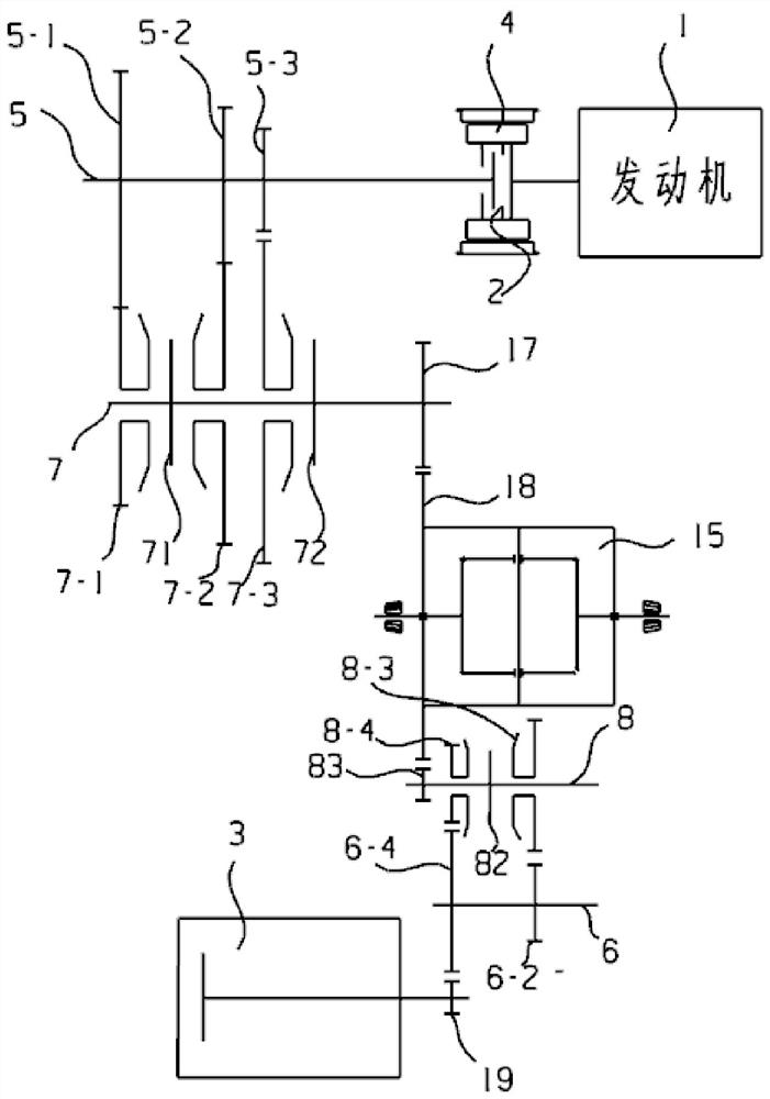
[0036] Such as image 3 , the first transmission assembly mostly includes a first driving gear 5-1, a second driving gear 5-2, a third driving gear 5-3, a first driven gear 7-1, a second driven gear 7-2, a Three driven gears 7-3, the first synchronizer 71, the second synchronizer 72, the first transmission gear 17, wherein, the first driving gear 5-1, the second driving gear 5-2, the third driving gear 5- 3 are respectively fixed with the input shaft 5, and the first driven gear 7-1, the second driven gear 7-2, and the third driven gear 7-3 are respectively vacantly sleeved on the intermediate shaft 7.

[0037] The first driving gear 5-1 meshes with the first driven gear 7-1 to form the first gear pair, and the second driving gear 5-2 meshes with the second driven gear 7-2 to form the second gear pair. The third driving gear 5-3 meshes with the third driven gear 7-3 to form a third gear pair.

[0038] The first synchronizer 71 is fixed on the intermediate shaft 7 and is loca...


PUM


Abstract

The invention provides a multi-mode hybrid drive system. A input shaft, an intermediate shaft, a first transmission shaft and a second transmission shaft are arranged in parallel, one end of the input shaft is connected with the crankshaft output end of an engine through a clutch, the clutch is arranged in a rotor of a second motor, an outer hub of the clutch is fixedly connected with the rotor of the second motor, the crankshaft output end of the engine is fixedly connected with the outer hub of the clutch in the circumferential direction, a driving friction disc of the clutch is fixedly connected with the outer hub, a driven friction disc of the clutch is fixedly connected with the input shaft, a third transmission assembly is arranged on the first transmission shaft, a fourth transmission assembly is arranged on the second transmission shaft, the third transmission assembly matches the fourth transmission assembly, the third transmission assembly further matches the first motor, and the fourth transmission assembly further matches a differential mechanism. The multi-mode hybrid drive system has the characteristics that the structure is simple, and the driving system tends to be miniaturized.

Description

technical field [0001] The invention relates to the field of hybrid electric vehicles, in particular to a multi-mode hybrid electric drive system. Background technique [0002] Traditional fuel vehicles usually use petroleum as an energy source. With the shortage of resources and the environmental pollution caused by vehicle exhaust emissions, the country's restrictions on vehicle exhaust emissions are becoming more and more stringent. New energy vehicles with low emissions and low fuel consumption. However, pure electric vehicles in new energy vehicles have problems that are difficult to solve in the short term, such as high vehicle cost, long charging time, and unstable battery life. It has the advantages of both the pure electric vehicle and a variety of efficient driving modes, which can be driven by the engine and the first electric motor simultaneously, and can also be driven by the engine or the first electric motor alone. [0003] At present, hybrid vehicles usuall...

Claims


Application Information

Patent Timeline
Patent Type & Authority Applications(China)
IPC IPC(8): B60K6/22B60K6/36B60K6/40
CPCB60K6/22B60K6/36B60K6/40Y02T10/92
Inventor 郭星罗会兵洪波李益华黄俊童廖梦琦谢运军邓仕林陈梅严博廖金龙
Owner CHONGQING TSINGSHAN IND
Learn More