
Chip liquid cooling and separating device and five-axis machining center

A five-axis machining center, cooling and separation technology, applied in the direction of metal processing equipment, metal processing machinery parts, manufacturing tools, etc., can solve the problems of small particle size of metal powder, blockage of screen holes, low screening efficiency, etc., to reduce requirements, avoid clogging and inefficiencies, facilitate cooling effects

Pending Publication Date: 2021-11-16
安徽省安达兴智能装备有限公司
View PDF2 Cites 0 Cited by
  • Summary
  • Abstract
  • Description
  • Claims
  • Application Information

AI Technical Summary

Problems solved by technology

[0006] However, the existing cutting fluid recovery devices basically use filtration to separate metal chips from cutting fluid. This method is easier to separate larger metal wires and metal particles, but the particle size of the metal powder formed by processing is extremely small. On the one hand, it is difficult to sieve with ordinary sieves. On the other hand, even if sieves are sieved with a drying net that meets the requirements, because the sieve aperture is too small, not only the sieving efficiency is relatively low, but also the sieve holes will appear. The phenomenon of being blocked

Method used


Image

  • Chip liquid cooling and separating device and five-axis machining center
  • Chip liquid cooling and separating device and five-axis machining center
  • Chip liquid cooling and separating device and five-axis machining center

Examples


Embodiment

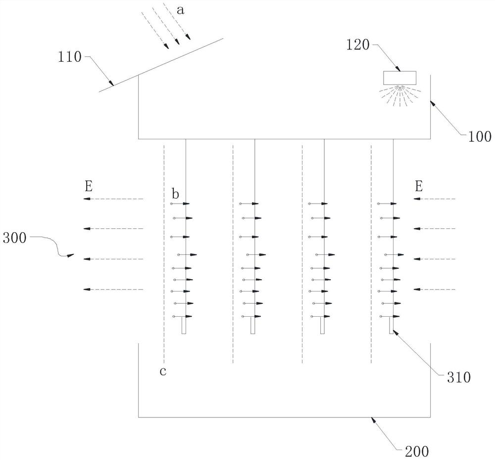
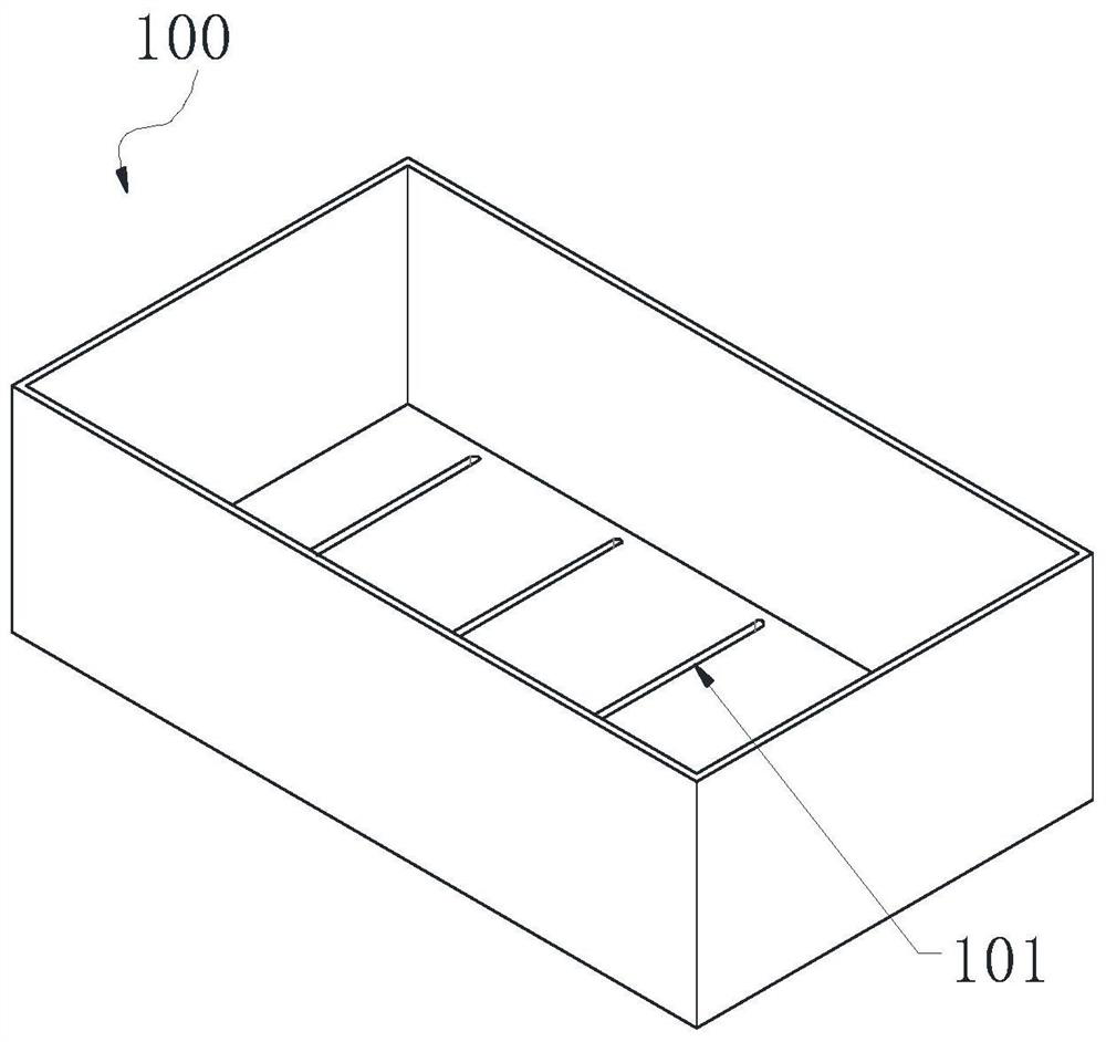
[0026] Such as figure 1 Shown is the chip liquid cooling and separating device of the present invention, the chip liquid cooling and separating device includes a No. 1 liquid collection tank 100 and a No. 2 liquid collection tank 200, wherein the No. Above, the top of the No. 1 liquid collecting tank 100 is also provided with a preliminary screen 110, and an electron gun 120 is installed in the No. 1 liquid collecting tank 100, and an interval is set between the No. 1 liquid collecting tank 100 and the No. 2 liquid collecting tank 200, and An electric field area 300 is provided between the No. 1 liquid collection tank 100 and the No. 2 liquid collection tank 200 , and the bottom of the No. 1 liquid collection tank 100 has a liquid leakage hole 101 .

[0027] The collected cutting fluid is screened through the primary screen 110, such as figure 1 As shown by the arrow a in the middle, the primary screen 110 mainly screens out granular and filamentous metal waste, and the remai...


PUM


Abstract

The invention discloses a chip liquid cooling and separating device and a five-axis machining center comprising the same. The chip liquid cooling and separating device sequentially comprises a primary screen, a first liquid collecting box, an electric field area and a second liquid collecting box from top to bottom; the primary screen is used for primarily screening out chips, with large particle sizes, carried in chip liquid; the first liquid collecting box is an insulator, the first liquid collecting box is used for collecting the chip liquid screened by the primary screen, an electron gun for emitting electrons to the chip liquid to enable the metal chips to form charged particles is arranged in the first liquid collecting box, and liquid leakage holes are further formed in the bottom of the first liquid collecting box; the electric field area provides any electric field which is not parallel to a water curtain. According to the chip liquid cooling and separating device and the five-axis machining center, the requirement on the screen can be greatly reduced, and meanwhile, the conditions of blockage and low efficiency caused by the fact that the screen is used only can be avoided; the separation efficiency and the separation rate of the metal chips in the chip liquid can be improved through the electric field; and the heat dissipation area of the cutting fluid is multiplied by the water curtain formed during electric field separation, so that the heat dissipation efficiency is greatly improved.

Description

technical field [0001] The invention belongs to the technical field of machining centers, in particular to a chip liquid cooling and separating device and a five-axis machining center. Background technique [0002] In the field of modern mechanical processing, as a high-precision automatic processing equipment, machining centers are more and more applied to high-precision Parts are being processed. Especially for some small batch parts with complex shapes and high precision requirements, the processing method is often completed by high-precision machining centers. [0003] Machining centers are often used to process precise and complex metal parts, and different tools are used to process metal blanks. When the machining center is processing, it will need to spray cutting fluid to the processing part at the same time. On the one hand, it is to cool down the tool and avoid thermal damage to the cutter head. Wrap around the cutter head or the surface of the workpiece to caus...

Claims


Application Information

Patent Timeline
IPC IPC(8): B23Q11/00B23Q11/10C02F9/00
CPCB23Q11/0042B23Q11/10C02F9/00C02F1/001C02F1/305C02F1/48
Inventor 吴人勇吴锦松胡俊杰
Owner 安徽省安达兴智能装备有限公司
Learn More