

Power module internal connection copper sheet, preparation method thereof, and power semiconductor module
A power semiconductor and internal connection technology, applied in the fields of semiconductor devices, semiconductor/solid-state device manufacturing, semiconductor/solid-state device components, etc. Small secondary molding difficulty, improved molding yield, and reduced effect of mechanical fracturing
- Summary
- Abstract
- Description
- Claims
- Application Information
AI Technical Summary
Problems solved by technology
Method used
Image

Examples
Embodiment 1
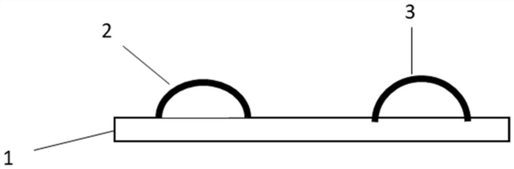
[0045] Such as Figure 1~3 As shown, a power module internal connection copper sheet provided by the present invention includes a copper plate 1, a first copper strip 2 and a second copper strip 3, the first copper strip 2 and the second copper strip 3 are arranged on the copper plate 1 at intervals, Both the first copper strip 2 and the second copper strip 3 are arc-shaped; The copper plate 1 is hollow. The width of the first copper strip 2 is 2000um, and the thickness of the first copper strip 2 is 200um. The width of the second copper strip 3 is 2000um, and the thickness of the second copper strip 3 is 200um.
[0046] The present invention also provides a preparation method based on the above-mentioned internal connection copper sheet of the power module, comprising the following steps:
[0047] Step 1: connecting the arc-shaped first copper strip 2 and the arc-shaped second copper strip 3 to the copper plate 1 by bond bonding process;
[0048] Step 2: Insert correspond...
Embodiment 2
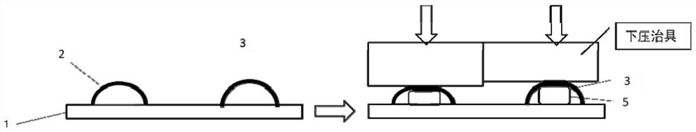
[0053] Such as Figure 4~6 As shown, the difference from Embodiment 1 is that a through hole 4 is provided on the copper plate 1 corresponding to the position below the first copper strip 2 and the second copper strip 3 .
[0054] The present invention also provides a preparation method based on the above-mentioned internal connection copper sheet of the power module, comprising the following steps:
[0055] Step 1: place the arc-shaped first copper strip 2 and the arc-shaped second copper strip 3 corresponding to the perforation 4 on the copper plate 1,
[0056] Step 2: Connect the first copper strip 2 and the second copper strip 3 to the copper plate 1 by bond bonding process;
[0057] Step 3: pass and fix the metal strip 5 that needs to support the first copper strip 2 and the second copper strip 3 through the perforation 4, and support the first copper strip 2 and the second copper strip 3;
[0058] Step 4: Position the copper plate 1 on the forming jig, and carry out pr...
Embodiment 3
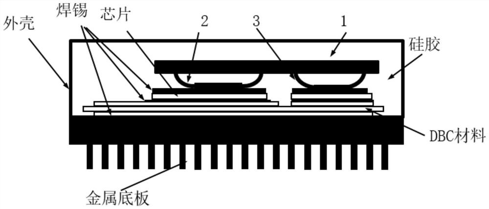
[0062] Such as image 3 and Figure 7 As shown, the difference from Embodiment 1 is that the first copper strip 2 and the second copper strip 3 are integrally formed.
[0063] The present invention also provides a preparation method based on the above-mentioned internal connection copper sheet of the power module, comprising the following steps:
[0064] Step 1: Install a looper on the welding head;
[0065] Step 2: Bind the copper strip to the copper plate 1;
[0066] Step 3: Draw wire arcs on the copper tape and form it into the final platform shape at one time.
[0067] In this embodiment, in the process of welding the binding wire or ribbon to the copper plate, loop forming is added to the wire bonding equipment for one-time forming, and no secondary forming process is required.
[0068] In a preferred example, during the process of welding the binding wire or ribbon to the copper plate, a loop former is installed on the welding head of the wire welding equipment, and ...
PUM
 Abstract
Description
Claims
Application Information