Capacity control valve

A capacity control and valve core technology, applied in control valve, non-electric variable control, fluid pressure control and other directions, can solve the problems of large size, unable to smoothly control the opening and closing adjustment of valve core, etc.

Pending Publication Date: 2021-11-16
EAGLE INDS
View PDF11 Cites 0 Cited by
  • Summary
  • Abstract
  • Description
  • Claims
  • Application Information

AI Technical Summary

Problems solved by technology

However, since the opposite surface of one iron core is a truncated cone shape, and the opposite surface of the other iron core is a concave shape complementary to the truncated cone shape, the two iron cores are mutually concave-convex and clearance fit shapes, therefore, there is The following problem: In the case of increasing the axial thrust of the maximum stroke position of the spool, the overall structure will be enlarged. On the other hand, when the separation distance between the two iron cores at the maximum stroke position of the spool becomes larger In the case of a small arrangement structure, the magnetic force acting on the inclined facing surfaces increases due to the approach of the axial direction, and the fine opening and closing adjustment of the valve core cannot be smoothly controlled.

Method used


Image

  • Capacity control valve
  • Capacity control valve
  • Capacity control valve

Examples


Embodiment 1

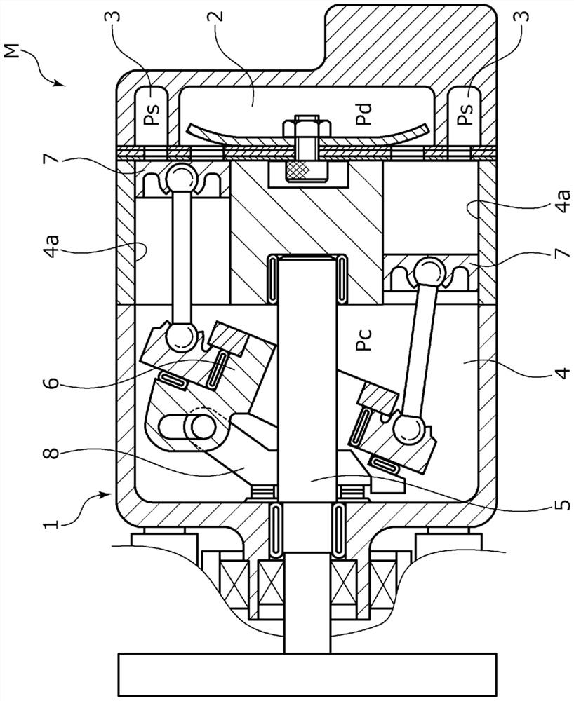
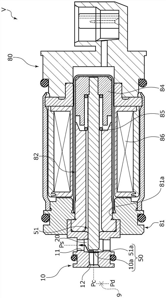
[0048] refer to Figure 1 to Figure 7 , the capacity control valve of Embodiment 1 will be described. Below, will be from figure 2 The left and right sides when viewed from the front side are described as the left and right sides of the capacity control valve.

[0049] The capacity control valve V of the present invention is incorporated in a variable capacity compressor M used in an air-conditioning system such as an automobile, and controls the pressure of a working fluid (hereinafter simply referred to as "fluid"), which is a refrigerant, variably, thereby controlling a variable The displacement of the capacity compressor M adjusts the air conditioning system to the desired refrigeration capacity.

[0050] First, the variable displacement compressor M will be described. Such as figure 1 As shown, the variable displacement compressor M has a casing 1 including a discharge chamber 2, a suction chamber 3, a control chamber 4, and a plurality of cylinders 4a. In addition,...

Embodiment 2

[0084] refer to Figure 8 and Figure 9 , the capacity control valve of Embodiment 2 will be described. In addition, with regard to the same structure as that of the above-mentioned embodiment 1, repeated descriptions are omitted.

[0085] Such as Figure 8 As shown, the center column 94 has a convex portion 95 formed to protrude toward the side facing the movable iron core 84 . The convex portion 95 is formed on the outer diameter side, has a tapered shape, and has an outer peripheral surface 95 b that extends over the front end surface 95 a and is inclined with respect to the axial direction of the center column 82 . The inner peripheral surface 95 c of the convex portion 95 forms a surface parallel to the axial direction of the center column 94 . In addition, on the radially inner side of the base of the convex portion 95 , an opposing surface 96 serving as the inner end of the concave portion is formed, which is perpendicular to the axial direction of the center column...

Embodiment 3

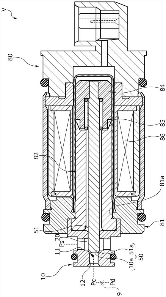
[0092] refer to Figure 10 , the capacity control valve of Embodiment 3 will be described. In addition, with regard to the same structure as that of the above-mentioned embodiment 1, repeated descriptions are omitted.

[0093] When the capacity control valve V2 is in the non-energized state, the force of the coil spring 85 presses the movable iron core 84 axially to the right, thereby, the CS spool 151 moves axially to the right, and the large diameter of the CS spool 151 The axial right side of the portion 151a is seated on the CS valve seat 110a, and the CS valve 150 is closed. And, in the energized state (i.e., during normal control, so-called duty ratio control), by applying current to the solenoid 80, the movable iron core 84 is drawn closer to the center column 82 side, that is, to the left side in the axial direction. , the CS spool 151 fixed to the movable iron core 84 moves axially leftward together, whereby the axial right side of the large-diameter portion 151a of...


PUM


Abstract

The objective of the present invention is to provide a capacity control valve in which a valve body can be controlled smoothly, and in which the valve body can be held stably in a maximum stroke position. In a capacity control valve (80) in which energization of an electromagnetic coil (86) causes a movable iron core (84) to move toward a fixed iron core (82) due to the attraction of a magnetic force, thereby causing the position of a valve body (51) to change. One iron core (82) is provided with a protruding portion (90) on the diametrically outer side thereof; the other iron core (84) is provided with a protruding portion (92) on the diametrically inner side thereof; the protruding portions are capable of fitting loosely together when moved by attraction. An effective magnetic force surface (90a) of a tip end of one protruding portion (90) is formed to be smaller than an opposing surface (93) facing the opposing iron core (84), and is formed with a tapered shape.

Description

technical field [0001] The present invention relates to a capacity control valve for variably controlling the capacity of a working fluid, for example, a capacity control valve for controlling the discharge rate of a variable capacity compressor used in an automobile air conditioning system according to pressure. Background technique [0002] A variable displacement compressor used in an air-conditioning system such as an automobile includes a rotating shaft driven by an engine, a swash plate connected to the rotating shaft at a variable inclination angle, and a compression piston connected to the swash plate. The stroke amount of the piston is changed by changing the inclination angle of the swash plate, thereby controlling the discharge amount of the fluid. Using a capacity control valve that is driven to open and close by electromagnetic force, the suction pressure Ps of the suction chamber that sucks in fluid, the discharge pressure Pd of the discharge chamber that disch...

Claims


Application Information

Patent Timeline
Patent Type & Authority Applications(China)
IPC IPC(8): F04B27/18F16K31/06
CPCF04B27/18F16K15/148F16K31/0655F16K31/0675F04B27/22F04B27/0843F04B27/1804F04B2027/1831F04B53/1082F16K31/06G05D16/2022
Inventor 叶山真弘福留康平神崎敏智高桥涉白藤啓吾
Owner EAGLE INDS
Why Eureka
Try Eureka