Installation and construction method of steel reinforced concrete column and steel beam connection joint area

A technology for connecting nodes and concrete columns, which is applied in the field of installation and construction in the connection node area between steel concrete columns and steel beams, can solve the problems that the formwork cannot be reinforced, the workload of stirrup welding increases, and the length of the cantilever is large, etc. Pouring phenomenon, reduced welding workload, and reduced damage to steel structures

Pending Publication Date: 2021-11-19
THE THIRD CONSTR OF CHINA CONSTR EIGHTH ENG BUREAU
View PDF3 Cites 2 Cited by
  • Summary
  • Abstract
  • Description
  • Claims
  • Application Information

AI Technical Summary

Problems solved by technology

[0003] The traditional method of binding steel bars and formwork support will cause the open stirrup of the steel column to pass through the hole of the corbel, and weld to form a closed stirrup of the column. The bearing capacity of the web part is reduced, the internal stress of the steel plate is redistributed, the construction quality of the steel bar cannot be guaranteed, and there are structural safety risks
In addition, the entire slab cannot be used at the joints of beams and columns when the formwork is supported, and the formwork at the joints cannot be reinforced, and the quality of the concrete forming surface after the concrete pouring is poor, the phenomenon of grout leakage is serious, the quality risk is high, and the process is cumbersome
In addition, it is difficult to lay the reinforced truss floor deck at the frame column, the length of the cantilever is large, and there is no effective support.

Method used


Image

  • Installation and construction method of steel reinforced concrete column and steel beam connection joint area
  • Installation and construction method of steel reinforced concrete column and steel beam connection joint area
  • Installation and construction method of steel reinforced concrete column and steel beam connection joint area

Examples


Embodiment

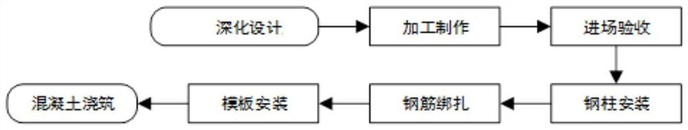
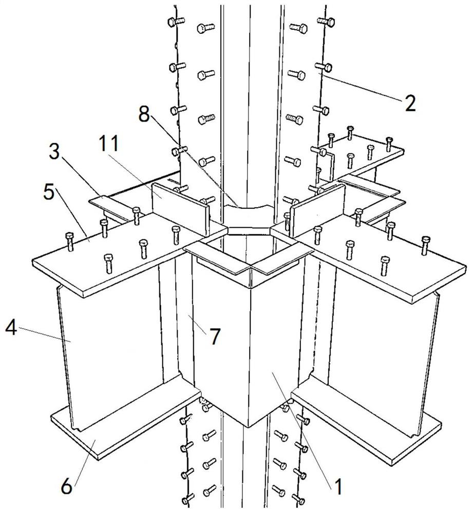
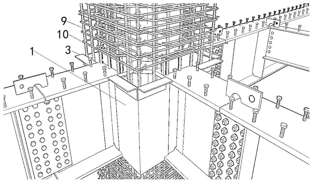
[0033] Such as Figure 1-3 As shown, a method for installation and construction of a joint area between a steel concrete column and a steel beam includes the following steps:

[0034] S1. In-depth design: optimize the connection node area between the steel column and the steel beam, use the steel structure hoarding 1 to replace the original stirrup, carry out typesetting and force calculation on the steel structure hoarding 1, and confirm the size of the steel structure hoarding 1 , position and elevation to form a steel structure deepening diagram; wherein, the yield strength of the steel structure hoarding 1 is greater than that of the steel column 2, and the cross-sectional area of ​​the steel structure hoarding 1 is calculated by equal strength replacement, and the steel structure hoarding 1 The thickness is greater than the diameter of the original stirrup. The steel structure hoarding 1 is designed to meet the requirements of the seismic grade, and the original stirrups...


PUM


Abstract

The invention provides an installation and construction method of a steel reinforced concrete column and steel beam connecting joint area. The installation and construction method comprises the following steps that S1, deepening design is carried out; S2, processing and manufacturing are carried out; S3, entrance acceptance is carried out; S4, steel columns are installed; S5, reinforcing steel bars are bound; S6, formworks are installed; and S7, concrete pouring is carried out. A steel structure coaming is adopted to replace stirrups and formworks in the section steel concrete column connection joint area, and the construction quality of the section steel column and steel beam connection joint area is improved.

Description

technical field [0001] The invention relates to the technical field of connecting a shaped steel column and a steel beam, in particular to an installation and construction method for a joint area between a shaped steel concrete column and a steel beam. Background technique [0002] In recent years, my country is in the process of rapid development of the construction industry, and at the same time, the construction industry is gradually transforming to green buildings and the modernization of the construction industry. The steel frame of the steel concrete column is a cross-shaped steel column, the core area of ​​the column joint is the dense area of ​​the column stirrup, and the corbel is set on the side with the steel beam. [0003] The traditional method of binding steel bars and formwork support will cause the open stirrup of the steel column to pass through the hole of the corbel, and weld to form a closed stirrup of the column. The bearing capacity of the web part is ...

Claims


Application Information

Patent Timeline
Patent Type & Authority Applications(China)
IPC IPC(8): E04B1/30E04B1/58E04C5/03E04G21/14E04G21/02E04G21/06E04G21/24E04G13/02
CPCE04B1/30E04B1/5812E04C5/03E04G21/14E04G21/02E04G21/06E04G21/246E04G13/02
Inventor 崔进付效铎张宝云苟生贵全有维
Owner THE THIRD CONSTR OF CHINA CONSTR EIGHTH ENG BUREAU
Why Eureka
Try Eureka