

Radiotherapy target region establishment and correction method based on dose distribution preview system
A technology of dose distribution and target volume, applied in the computer field, can solve the problems of reduced treatment time, insufficient external expansion of the PTV boundary, and lack of overall dose distribution prediction, so as to improve the rationality and the quality of radiotherapy plans, and shorten the treatment delay. time, effectiveness of streamlining target modification and planning processes
- Summary
- Abstract
- Description
- Claims
- Application Information
AI Technical Summary
Problems solved by technology
Method used
Image

Examples
Embodiment Construction
[0050] The following will clearly and completely describe the technical solutions in the embodiments of the present invention with reference to the accompanying drawings in the embodiments of the present invention. Obviously, the described embodiments are part of the embodiments of the present invention, but not all of them. Based on the embodiments of the present invention, all other embodiments obtained by persons of ordinary skill in the art without making creative efforts belong to the protection scope of the present invention.
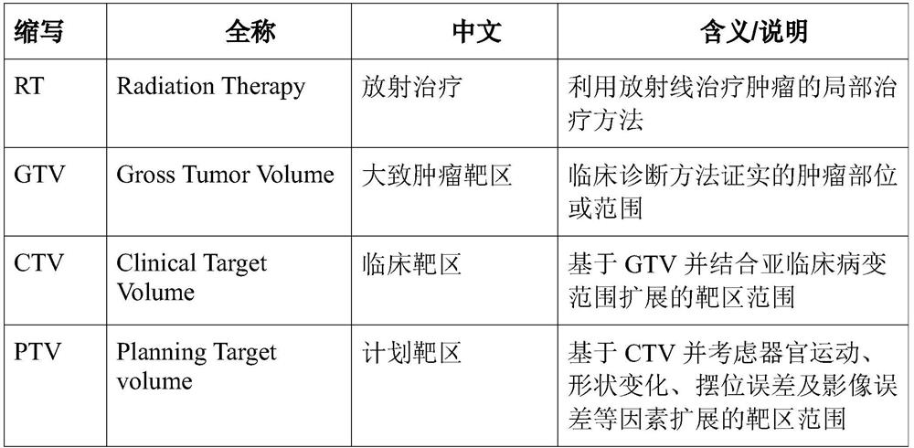
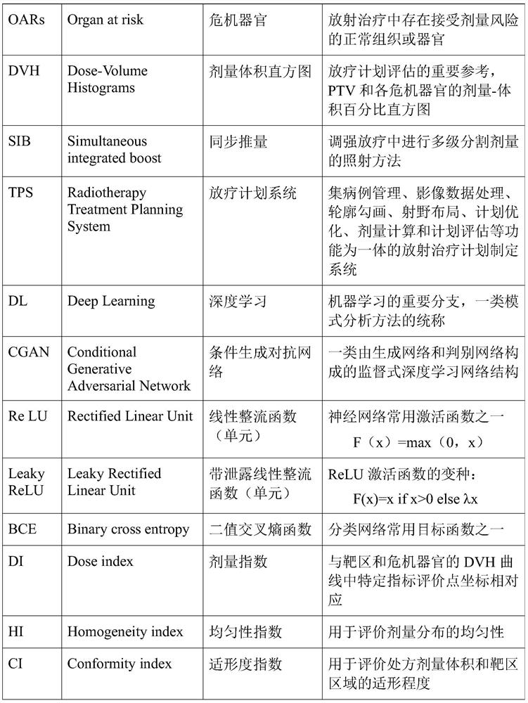
[0051] Abbreviations and key terms involved in the embodiments of the present invention are defined in the following table:
[0052]
[0053]
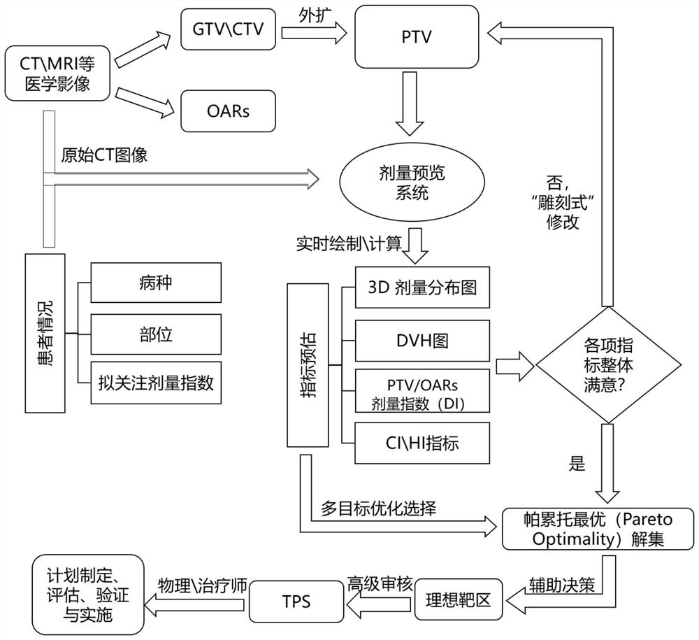
[0054] The inventive idea of the present invention is that in recent years, deep learning technology has been widely used in the field of radiotherapy, mainly involving automatic diagnosis, automatic segmentation and dose prediction. The present invention first relies on the collection of a large n...
PUM
 Abstract
Description
Claims
Application Information