Environment-friendly flue gas desulfurization system

A desulfurization system and environmental protection technology, applied in the direction of cleaning hollow objects, fixed filter elements, cleaning methods and appliances, etc., can solve the problems of high labor costs, troublesome operation, and large volume of flue gas desulfurization towers, etc., to improve practicability , improve the impact force, and ensure the effect of normal function

Inactive Publication Date: 2021-11-23
张志超
View PDF0 Cites 2 Cited by
  • Summary
  • Abstract
  • Description
  • Claims
  • Application Information

AI Technical Summary

Problems solved by technology

[0004] Although the above-mentioned patent can be provided with a filter screen in the pipeline, it is inevitable that some dust will fall into the absorption liquid storage chamber in the filter plate. Filtration to avoid clogging, but in actual work, after using the filter to filter the kiln tail gas desulfurization, the calcium sulfate and calcium sulfite solids contained in the liquid precipitate, and the fine particles of the precipitate are easy to be separated from the filter under the action of inertia when they follow the flow of the liquid. The surface of the net collides with each other, thus forming accumulations. After a long time, the filtered impurities will also block the pipeline, which needs to be cleaned regularly, and the operation is troublesome. At the same time, the product liquid generated during actual use contains a large amount of calcium sulfate and calcium sulfite. Solid deposits will scale and adhere to the inner wall of the flue gas desulfurization tower. The above-mentioned patent does not have a cleaning mechanism, and personnel are required to clean it later. Due to the relatively large volume of the flue gas desulfurization tower, it requires high labor costs and is inconvenient for cleaning personnel to clean up.

Method used


Image

  • Environment-friendly flue gas desulfurization system
  • Environment-friendly flue gas desulfurization system
  • Environment-friendly flue gas desulfurization system

Examples


Embodiment Construction

[0032] The following will clearly and completely describe the technical solutions in the embodiments of the present invention with reference to the accompanying drawings in the embodiments of the present invention. Obviously, the described embodiments are only some, not all, embodiments of the present invention. Based on the embodiments of the present invention, all other embodiments obtained by persons of ordinary skill in the art without making creative efforts belong to the protection scope of the present invention.

[0033] In describing the present invention, it is to be understood that the terms "center", "longitudinal", "transverse", "length", "width", "thickness", "upper", "lower", "front", " Back", "Left", "Right", "Straight", "Horizontal", "Top", "Bottom", "Inner", "Outer", "Clockwise", "Counterclockwise", etc. or The positional relationship is based on the orientation or positional relationship shown in the drawings, which is only for the convenience of describing t...


PUM


Abstract

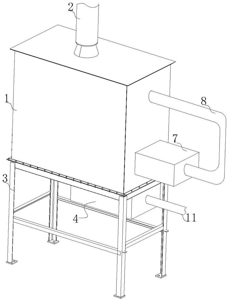
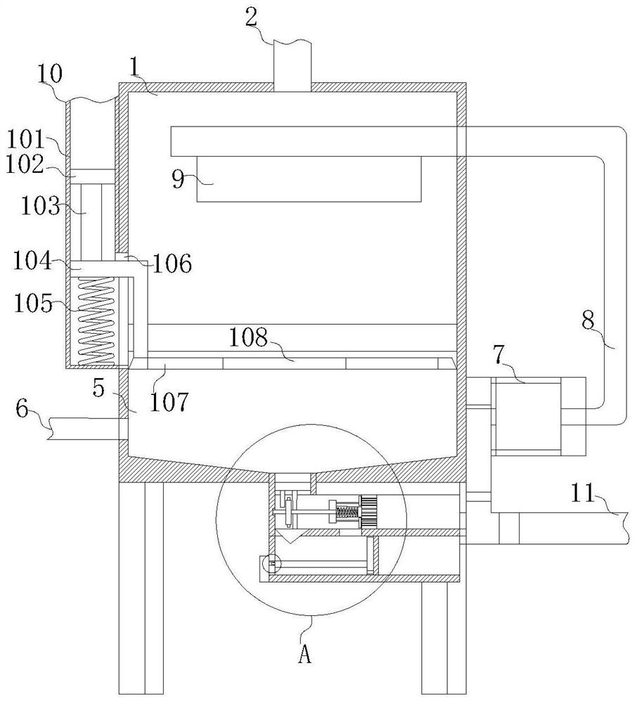
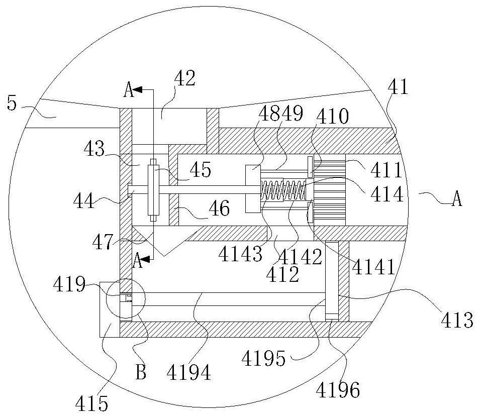
The invention discloses an environment-friendly flue gas desulfurization system. The system comprises a desulfurization tower body. A gas outlet is connected to the outer surface of the upper end of the desulfurization tower body in a penetrating mode. Four sets of supporting columns are fixedly installed at the positions, close to the edge, of the outer surface of the lower end of the desulfurization tower body. According to the device, an anti-blocking shell can be arranged, when water enters the anti-blocking shell from a water storage cavity and enters a flowing cavity through a second water inlet, the impact force of the water flow drives a fan to rotate, so that the problem that in actual work, after the furnace tail gas is filtered by a filter screen for desulfurization, fine calcium sulfate and calcium sulfite solid precipitate particles contained in the generated liquid can easily collide with and contact the surface of the filter screen and be stacked under the inertia effect when flowing along with the liquid, and a pipeline is blocked by filtered impurities after long time is avoided, it is guaranteed that the filter screen normally plays a role, and the overall practicability is improved.

Description

technical field [0001] The invention relates to the technical field of flue gas treatment, in particular to an environment-friendly flue gas desulfurization system. Background technique [0002] Desulfurization generally refers to the desulfurization process of removing sulfur from fuel before combustion and flue gas discharge. It is one of the important technical measures to prevent and control air pollution. At present, desulfurization methods generally include desulfurization before combustion, during combustion and after combustion. One, with the development of industry and the improvement of people's living standards, the thirst for energy is also increasing. SO2 in coal-fired flue gas has become the main cause of air pollution, and reducing SO2 pollution has become the top priority of today's atmospheric environmental governance. The less flue gas desulfurization process has been widely used in industry, and it also has important practical significance for the treatmen...

Claims


Application Information

Patent Timeline
Patent Type & Authority Applications(China)
IPC IPC(8): B01D53/78B01D53/50B01D29/01B01D29/64B08B9/087B08B13/00
CPCB01D53/504B08B9/087B08B13/00B01D29/01B01D29/6476
Inventor 张志超刘方海
Owner 张志超
Why Eureka
Try Eureka