Brake

A brake and movable plate technology, applied in the direction of brake type, brake parts, brake disc, etc., can solve the problems of increasing wear rate, weakening coil magnetic field, braking torque attenuation, etc., to reduce jitter and drag torque, The effect of improving the overall structural strength and reducing the probability of creep

Active Publication Date: 2021-11-23
ALTRA IND MOTION SHENZHEN CO LTD
View PDF10 Cites 0 Cited by
  • Summary
  • Abstract
  • Description
  • Claims
  • Application Information

AI Technical Summary

Problems solved by technology

[0004] (1) If the thickness of the yoke is reduced, the coil space will be reduced, the coil magnetic field will be weakened or the heating power of the coil will be increased;
[0005] (2) After the thickness of the armature, friction disc and tail plate is thinned (the ratio of diameter to thickness is increased), the overall rigidity is weakened, and creep is easy to occur, or stress deformation or thermal stress deformation occurs during work. The temperature rises quickly in the medium (because of less material and small heat capacity), it is easy to cause braking torque attenuation or even completely damage the brake;
[0006] (3) After the thickness of the friction disc is reduced, the structural strength is insufficient, the processing difficulty increases, the verticality between the middle hole and the friction surface is poor, and the matching length with the shaft or bushing is small, the friction disc is prone to swing during rotation, Make abnormal noise and increase the drag torque; when rotating at high speed, the surface of the friction disc is also easily ablated locally, thereby reducing the friction torque and affecting the braking effect and safety;
[0007] (4) The extremely thin friction pair parts (armature, friction disc, tail plate) will amplify the noise (similar to the effect of the horn diaphragm) or make the noise sharper when rubbing;
[0008] (5) The friction radius of the friction disc is large, and the friction line speed at the same motor speed is high, sometimes exceeding the suitable working line speed of the material, increasing the wear rate and reducing the braking effect

Method used


Image

  • Brake
  • Brake
  • Brake

Examples


Embodiment Construction

[0058] In order to make the technical problems, technical solutions and beneficial effects to be solved by the present invention clearer, the present invention will be further described in detail below in conjunction with the accompanying drawings and embodiments. It should be understood that the specific embodiments described here are only used to explain the present invention, not to limit the present invention.

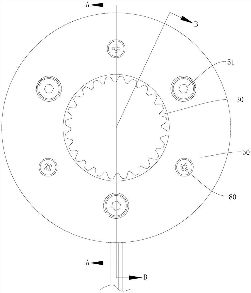
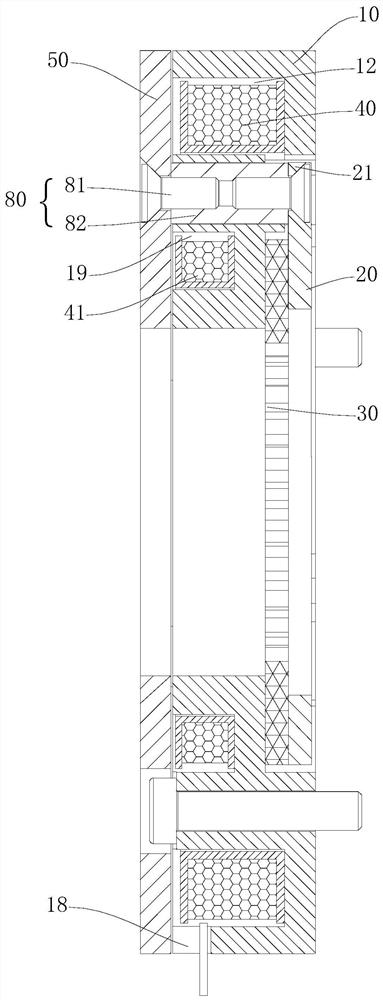
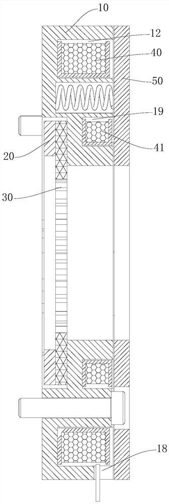
[0059] Please also refer to Figure 1 to Figure 18 , the brake provided by the present invention is now described. The brake includes a yoke core 10, a first movable plate 20, a friction disc 30, a first coil 40, a second coil 41, an armature 50 and an elastic member 60, and the yoke core 10 is concentrically distributed with the first An installation space 11 and a second installation groove 12, the first installation space 11 passes through the center of the yoke core 10 along the axial direction of the yoke core 10, and the opening of the second installation gr...


PUM


Abstract

The invention provides a brake which comprises a magnet yoke iron core, a first movable plate, a friction disc, a first coil, a second coil, an armature and an elastic piece. A first installation space and a second installation groove are sequentially and concentrically distributed in the magnet yoke iron core from inside to outside, the first installation space penetrates through the center position of the magnet yoke iron core in the axial direction of the magnet yoke iron core, the magnet yoke iron core is further provided with at least one third installation groove coaxial with the second installation groove, and the first movable plate is located in the first installation space; the friction disc is arranged in the first installation space and located on the side, close to the second shaft end, of the first movable plate; the first coil is arranged in the second installation groove; the second coil is arranged in the third installation groove; the armature is connected with the first movable plate through a connecting piece; and the elastic piece has a pre-tightening force which enables the armature to be far away from the magnet yoke iron core. The brake is relatively thin.

Description

technical field [0001] The invention belongs to the technical field of mechanical brakes, and in particular relates to a brake. Background technique [0002] There are open and closed brakes, no matter it is open or closed, the assembly method of the main parts is stacked, that is, the yoke, armature, friction disc and tail plate are stacked in sequence, although the structure is simple, but the whole is thicker. [0003] As the technical requirements for electromagnetic brakes are getting higher and higher, the thickness has gradually become a key parameter to measure the performance of the brakes. Especially in some special applications, the overall thickness of the brakes must be small, and the traditional stacked structure brakes can no longer meet the requirements. We can only rely on the use of better materials and finer processes to compress the thickness of the above-mentioned parts as much as possible to reduce the total stack thickness, which inevitably produces ot...

Claims


Application Information

Patent Timeline
IPC IPC(8): F16D65/00F16D65/12F16D65/22F16D121/22
CPCF16D65/0006F16D65/0031F16D65/12F16D65/22F16D2121/22
Inventor 鲁查吴孔建叶逸祥
Owner ALTRA IND MOTION SHENZHEN CO LTD
Why Eureka
Try Eureka