Energy-saving and environment-friendly industrial waste gas combustion treatment device

Inactive Publication Date: 2021-11-23
李艳程
View PDF0 Cites 0 Cited by
  • Summary
  • Abstract
  • Description
  • Claims
  • Application Information

AI Technical Summary

Problems solved by technology

[0004] The purpose of the present invention is to provide an energy-saving and environment-friendly industrial waste gas combustion treatment device, which has a better spray effect, and realizes dynamic control of the size of the combustion firepower and real-time adjustment of the spray effect, and has the advantages of energy saving, environmental protection and high utilization rate of resources Advantages, solve the problems raised by the background technology

Method used


Image

  • Energy-saving and environment-friendly industrial waste gas combustion treatment device
  • Energy-saving and environment-friendly industrial waste gas combustion treatment device
  • Energy-saving and environment-friendly industrial waste gas combustion treatment device

Examples


Embodiment 1

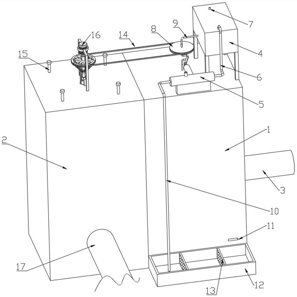
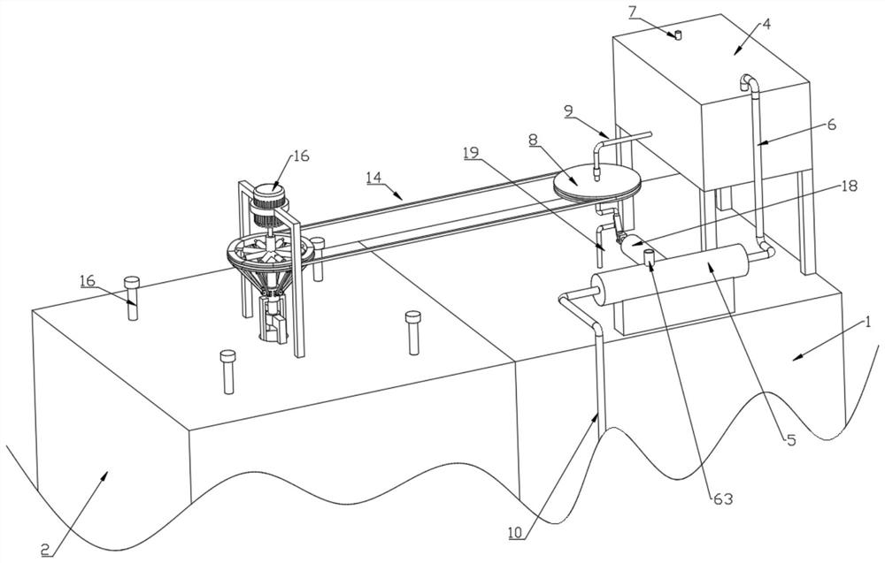
[0031] see figure 1 , figure 2 , Figure 4 , Figure 5 , Figure 6 , Figure 7 , an energy-saving and environment-friendly industrial waste gas combustion treatment device, comprising a spray tower 1 and an incinerator 2, the incinerator 2 is provided with a spray drive module, the spray drive module includes a combustion chamber 40, and the combustion chamber 40 is arranged on the incinerator 2 Inside, the inwall of combustion chamber 40 is provided with flame vent 39, and combustion chamber 40 is positioned at the position below flame vent 39 to be provided with air vent 62, and the upper end of combustion chamber 40 is provided with steam box 41, and steam box 41 is provided with water, steam box The upper end of 41 is provided with slide plate 42, and the upper end of slide plate 42 is fixedly connected with slide bar 15, and the upper end of slide bar 15 runs through the upper end of incinerator 2, and slide bar 15 is positioned at the end outer wall cover in inciner...

Embodiment 2

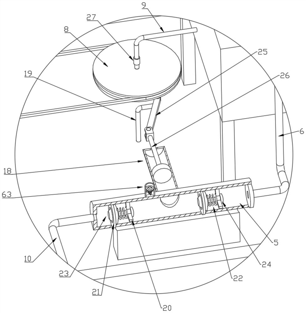
[0044] see Figure 12 , in this embodiment, other structures remain unchanged, and the present invention also provides another structural form of the nozzle 48. Preferably, the nozzle 48 is a tubular nozzle, and the nozzle 48 is bent and arranged obliquely on the third rocker. 61 lower end. The reaction force produced when the water flow is ejected from the shower nozzle 48 can push the rocker 3 61, so that the nozzle 48 rotates and sprays when the water guide pipe 19 is assisted.

[0045] The working principle of Embodiment 1 of this application: please refer to figure 1 , Figure 6 , Figure 7 , the exhaust gas passes into the spray tower 1 through the intake pipe 3, the water tank 4 passes water through the connecting pipe 9 into the water pipe 19, passes into the cross 55 through the water pipe 19, and passes through the water inlet pipe 260 on the cross 55. Rod 3 61 is finally sprayed out from the nozzle 48 to realize the function of settling the particles in the exha...


PUM


Abstract

The invention discloses an energy-saving and environment-friendly industrial waste gas combustion treatment device. The energy-saving and environment-friendly industrial waste gas combustion treatment device comprises a spraying tower and an incinerator; a spraying driving module is arranged on the incinerator; a combustion cavity is formed in the incinerator; a steam box is arranged at the upper end of the combustion cavity; water is arranged in the steam box; a sliding plate is arranged at the upper end of the steam box; the upper end of a sliding rod penetrates through the upper end of the incinerator; a second spring is arranged on the outer wall of the end, located in the incinerator, of the sliding rod in a sleeving mode; the upper end of a connecting rod is fixedly connected with a sliding sleeve; the upper end of the connecting sleeve is fixedly connected with a motor; an output shaft of the motor is fixedly connected with the upper end of a rotating shaft; a supporting rod is connected to the interior of a sliding cylinder in a limiting and sliding mode; multiple expansion blocks are arranged and form a complete circle; the outer wall of the sliding sleeve is rotationally connected with an ejector rod through a pin shaft; and the upper end of the ejector rod is rotationally connected to the lower surfaces of the expansion blocks through pin shafts. The energy-saving and environment-friendly industrial waste gas combustion treatment device has the advantages that the spraying effect is better, dynamic control of combustion firepower and real-time adjustment of the spraying effect are realized, and energy conservation, environmental protection and high resource utilization rate are achieved.

Description

technical field [0001] The invention relates to the technical field of waste gas combustion treatment, in particular to an energy-saving and environment-friendly industrial waste gas combustion treatment device. Background technique [0002] Waste gas treatment refers to the pretreatment of waste gas generated in industrial sites and factory workshops before being discharged to the outside, so as to meet the national standards for external discharge of waste gas. General waste gas treatment includes organic waste gas treatment, dust waste gas treatment, acid-base waste gas treatment, odor waste gas treatment and air sterilization, disinfection and purification. [0003] Since the exhaust gas contains incomplete oxides, it needs to be fully oxidized after combustion before it can be discharged. Since the exhaust gas also contains other harmful substances that need to be treated before it can be burned, most of the existing devices are integrated devices, which include a vari...

Claims


Application Information

Patent Timeline
Patent Type & Authority Applications(China)
IPC IPC(8): F23G7/06F23G5/50B01D47/06
CPCF23G7/06F23G5/50B01D47/06F23G2201/60F23G2209/14F23G2207/104Y02A50/2351
Inventor 李艳程
Owner 李艳程
Why Eureka
Try Eureka