Constant control shell and tube heat exchanger

A shell-and-tube heat exchanger and heat exchanger technology, which is applied in the improvement field of hotel waste heat recovery system, can solve the problems of high pressure, uneven heat transfer, high local temperature, etc., achieve optimal relationship optimization, increase vibration range, The effect of improving heating efficiency

Inactive Publication Date: 2021-11-23
青岛酒店管理职业技术学院
View PDF0 Cites 0 Cited by
  • Summary
  • Abstract
  • Description
  • Claims
  • Application Information

AI Technical Summary

Problems solved by technology

[0007] However, because the left tube and the right tube are independent structures, the pressure on the left and right sides is unbalanced or the liquid level is not balanced, which leads to uneven heat transfer on the left and right sides, resulting in high local temperature and even high pressure. Fatigue damage to heat exchange elements

Method used


Image

  • Constant control shell and tube heat exchanger
  • Constant control shell and tube heat exchanger
  • Constant control shell and tube heat exchanger

Examples


Embodiment Construction

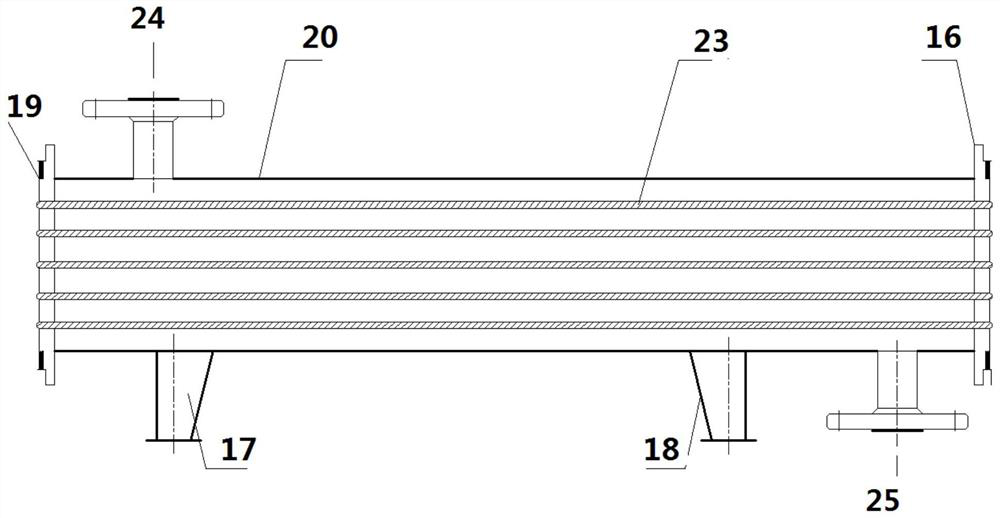
[0028] A shell-and-tube heat exchanger, such as figure 1 As shown, the shell-and-tube heat exchanger includes a shell 20, a heat exchange component 23, a shell side inlet connection 24 and a shell side outlet connection 25; the heat exchange component 23 is arranged in the shell 20, and the heat exchange component It is fixedly connected to the front tube sheet 16 and the rear tube sheet 19; the shell-side inlet connecting pipe 24 and the shell-side outlet connecting pipe 25 are both arranged on the shell 20; the fluid enters from the shell-side inlet connecting pipe 24 and passes through the heat exchange components. Heat exchange, take over 25 and go out from the shell side outlet.

[0029] Preferably, the heating member 23 extends along the vertical direction. The heat exchangers are arranged vertically.

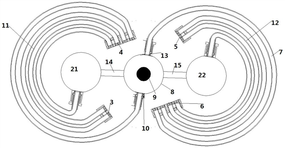
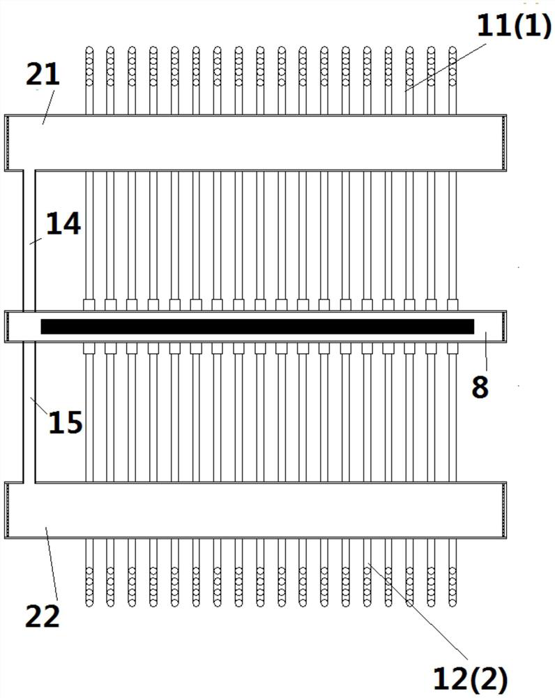
[0030] figure 2 A top view of the heat exchange component 23 is shown, as figure 2 As shown, the heat exchange component includes a central tube 8, a left side tube...


PUM


Abstract

The invention provides a constant control shell and tube heat exchanger. The heat exchanger comprises a shell, a heat exchange tube is arranged in the shell, the two ends of the heat exchange tube extend out of the shell, and the two ends of the heat exchange tube are connected to a pipeline between a compressor and a cooler; one side of the shell is connected with a water inlet tube, the other side of the shell is connected with a water outlet tube, and the water inlet tube is connected with a water supply system; and the water outlet tube is connected with a water collecting tank, a heating structure is arranged in the water collecting tank, and the heat exchange tube is spirally arranged in a cavity. According to the novel heat exchanger of a heat tube structure, heat balance of a left side tube and a right side tube is automatically regulated and controlled through temperature sensors arranged on the left side tube and the right side tube and a valve between the left side tube and the right side tube, and therefore it is guaranteed that heat exchange on the left side and the right side is uniform, and balance control over the system is achieved.

Description

technical field [0001] The invention relates to a shell-and-tube heat exchanger, in particular to an improvement of a hotel waste heat recovery system. Background technique [0002] Energy is the basic power to ensure the operation of various electromechanical equipment in hotels. With the rapid development of modern hotels in my country, although the energy management level of hotels has been greatly improved, and the energy consumption of hotels is showing a downward trend year by year, compared with developed countries, my country's hotel industry still has problems in terms of energy utilization efficiency. Big gap. It is specifically reflected in the fact that the condensation heat generated by the hotel air conditioner during the condensation process is not used, and is basically wasted with the discharge system; for this reason, a waste heat recovery system is urgently needed to recover the waste heat for secondary use. [0003] After fouling of the shell-and-tube he...

Claims


Application Information

Patent Timeline
Patent Type & Authority Applications(China)
IPC IPC(8): F28D7/16F28F27/02F28G7/00F24H9/00
CPCF28D7/1669F28F27/02F28G7/00F24H9/0005
Inventor 赵炜
Owner 青岛酒店管理职业技术学院
Why Eureka
Try Eureka