Millimeter wave antenna, antenna array and electronic equipment

A millimeter-wave antenna and array antenna technology, which is applied in the direction of separately powered antenna array, antenna coupling, resonant antenna, etc., can solve the problems of high processing cost and high cross-polarization components of millimeter-wave antennas, and reduce processing costs and reduce cross-polarization. Polarization component, the effect of suppressing high-order modes

Pending Publication Date: 2021-11-23
SHANGHAI AMPHENOL AIRWAVE COMM ELECTRONICS CO LTD
View PDF0 Cites 0 Cited by
  • Summary
  • Abstract
  • Description
  • Claims
  • Application Information

AI Technical Summary

Problems solved by technology

[0005] The technical problem to be solved by the present invention is to provide a millimeter-wave antenna, antenna array and electronic equipment to solve the problems of high processing cost and high cross-polarization components of existing millimeter-wave antennas

Method used


Image

  • Millimeter wave antenna, antenna array and electronic equipment
  • Millimeter wave antenna, antenna array and electronic equipment
  • Millimeter wave antenna, antenna array and electronic equipment

Examples


Embodiment 1

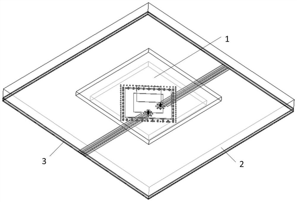
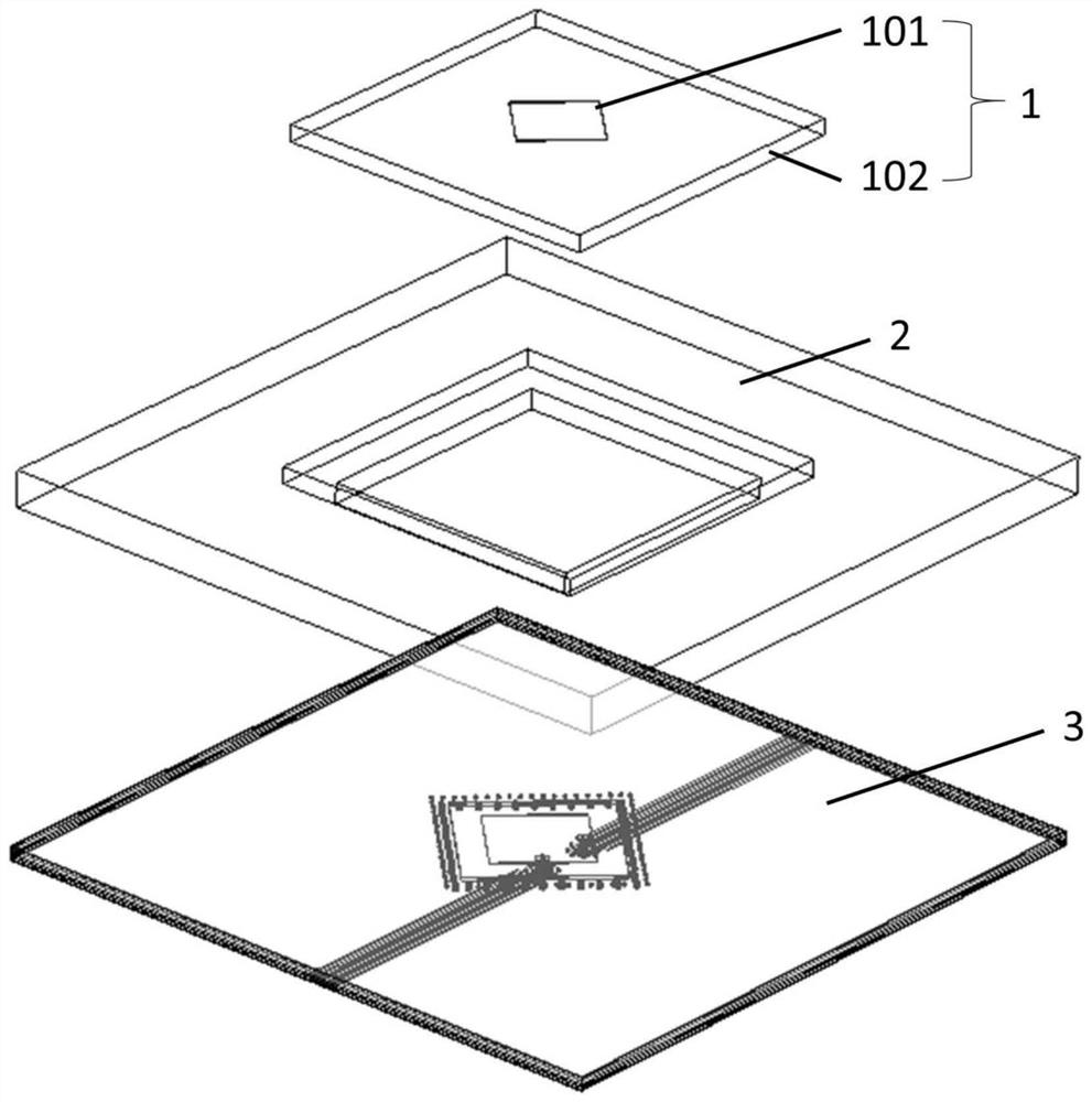
[0037] see Figure 1 to Figure 3 , In one embodiment, a millimeter wave antenna includes a first circuit board 1 , a wave absorbing layer 2 and a second circuit board 3 in order from top to bottom.

[0038] Wherein, the first circuit board 1 includes a first dielectric substrate 102 and a first radiation patch 101 , and the first radiation patch 101 is disposed on an upper surface or a lower surface of the first dielectric substrate 102 .

[0039] The upper surface of the absorbing layer 2 is attached to the lower surface of the first dielectric substrate 102 , and the lower surface of the absorbing layer 2 is attached to the upper surface of the second circuit board 3 . Moreover, a through groove is opened on the wave-absorbing layer 2 , and the through groove corresponds to the projection area of ​​the first radiation patch 101 on the second circuit board 3 .

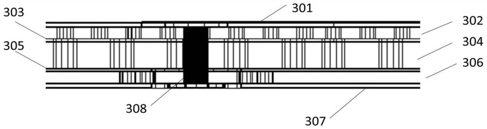
[0040] The second circuit board 3 includes a second radiation patch 301 , a feeder 307 , at least one signal hole,...

Embodiment 2

[0053] This embodiment provides a millimeter wave array antenna. On the basis of Embodiment 1, the number of millimeter wave antennas is increased to form a line array or an area array.

[0054] The linear array is a 1×N (N≥2 and a positive integer) antenna array, and N is the number of millimeter wave antennas. The size of N can be set according to the actual situation to realize simultaneous radiation of N antennas and form beam scanning in one-dimensional direction.

[0055] The area array is an N×M (N≥2, M≥2 and N and M are both positive integers) antenna array, that is, N antennas are set along the x direction, M antennas are set along the y direction, and the total number of antennas is N× M. The sizes of N and M can be set according to the actual situation. Such as Figure 6 As shown, it is a 4×4 antenna array, that is, 4 antennas are set along the x direction, and 4 antennas are set along the y direction. The total number of antennas is 16, and they are arranged at...

Embodiment 3

[0057] Based on the same concept, this embodiment provides an electronic device, including the millimeter wave antenna in Embodiment 1 or the array antenna in Embodiment 2.


PUM


Abstract

The invention discloses a millimeter wave antenna, an antenna array and electronic equipment. A first circuit board and a second circuit board are respectively arranged on two sides of a wave absorbing layer; the first circuit board comprises a first radiation patch and a first dielectric substrate from top to bottom; the second circuit board comprises a second radiation patch, a second dielectric substrate, a first floor, a third dielectric substrate and a feeder line from top to bottom, and is provided with a signal hole for connecting the second radiation patch and the feeder line; and the through groove is formed in the wave absorbing layer, so that the energy of the second radiation patch can be coupled to the first radiation patch to the maximum extent. The wave absorbing layer is arranged around the radiation patch, so that a high-order mode generated by the floor on the second circuit board can be suppressed, and the cross polarization component of the millimeter wave antenna is reduced; and meanwhile, the millimeter wave antenna is designed in a layered manner through the arrangement of the wave absorbing layer, the number of layers of the circuit board is reduced, the types of via holes are reduced, and the processing cost is further reduced.

Description

technical field [0001] The invention belongs to the technical field of antennas, and in particular relates to a millimeter wave antenna, an antenna array and electronic equipment. Background technique [0002] With the evolution of the fifth-generation communication technology, communication equipment should develop in the direction of low latency, high reliability and large bandwidth. Due to its short wavelength and wide bandwidth, millimeter wave can more easily meet these requirements, so it has gradually been pushed onto the stage of the fifth-generation communication technology. In order for millimeter-wave communication technology to take advantage of more obvious advantages, millimeter-wave antennas must meet the requirements of wide bandwidth, high isolation, high gain, and low cross-polarization, as well as low-cost processing requirements. [0003] At present, 5G millimeter-wave antennas usually use PCB multilayer board processing technology. Considering the integ...

Claims


Application Information

Patent Timeline
Patent Type & Authority Applications(China)
IPC IPC(8): H01Q9/04H01Q1/48H01Q1/52H01Q21/06
Inventor 王来军
Owner SHANGHAI AMPHENOL AIRWAVE COMM ELECTRONICS CO LTD
Why Eureka
Try Eureka