
Motor energy conversion charging device, method and system for new energy electric vehicle

An electric vehicle and energy conversion technology, applied in electric vehicle charging technology, output power conversion devices, electric vehicles, etc., can solve problems such as increased cost and safety, and achieve the effects of short charging time, mature control and low cost

Pending Publication Date: 2021-11-23
HUAZHONG UNIV OF SCI & TECH
View PDF3 Cites 0 Cited by
  • Summary
  • Abstract
  • Description
  • Claims
  • Application Information

AI Technical Summary

Problems solved by technology

[0006] There is a contradiction between charging power and charging time. If you want to increase the charging power and shorten the charging time, you need to increase the cost and bring safety issues

Method used


Image

  • Motor energy conversion charging device, method and system for new energy electric vehicle
  • Motor energy conversion charging device, method and system for new energy electric vehicle
  • Motor energy conversion charging device, method and system for new energy electric vehicle

Examples


Embodiment 1

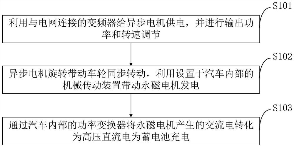
[0069] The driving device provided by the embodiment of the present invention includes an asynchronous motor and a frequency converter. The frequency converter is directly connected to the power grid. The frequency converter supplies power to the asynchronous motor to realize output power and speed adjustment. The capacity of the driving device is 60-200kVA, and the motor speed range is 0. -4000r / min.

[0070] The mechanical connection device provided by the embodiment of the present invention includes two parts. The first part includes the shaft of the asynchronous motor, the coupling and the hub of the car. The shaft of the asynchronous motor is connected with the hub of the car through the coupling to ensure that the asynchronous motor can drive the hub of the car synchronously. turn. The second part includes mechanical devices such as the drive shaft and reducer inside the car to ensure that the rotation of the car hub can be transmitted to the permanent magnet motor. The ...

Embodiment 2

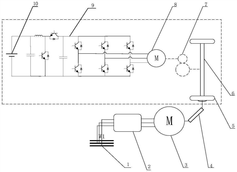
[0073] The driving device is powered by the 1-grid for the 2-inverter. The grid outputs three-phase 380V 50HZ voltage to supply power for the inverter. The capacity of the inverter is 60kVA. The 3-asynchronous motor is used as the driving motor, with a total of 8 poles and a rated power of 60kW. Through frequency conversion speed regulation, its speed range is 0-4000r / min. The rated speed is 3000r / min.

[0074] The mechanical device connects the shaft of the asynchronous motor with the 5-hub by a 4-coupling. The driving wheel of the car is placed on the free roller, and the shaft of the asynchronous motor rotates synchronously with the wheel of the electric car. The diameter of the wheel is 18 inches (45.72 cm). When the asynchronous motor works at the rated speed, the speed of the wheel is consistent with that of the motor, which is 3000r / min. That is 71.8km / h. The rotation of the wheel drives the 6-axle to rotate, and the speed is transmitted to the 8-permanent magnet moto...


PUM


Abstract

The invention belongs to the technical field of new energy electric vehicles, and discloses a motor energy conversion charging device, method and system of a new energy electric vehicle, and the motor energy conversion charging system of the new energy electric vehicle comprises a driving device, a mechanical connecting device and an in-vehicle charging device; the driving device comprises a frequency converter and an asynchronous motor; the mechanical connecting device comprises an asynchronous motor rotating shaft, an automobile hub, a coupler, a transmission shaft, a speed reducer and other mechanical devices, wherein the transmission shaft, a speed reducer and other mechanical devices are disposed in the vehicle; the in-vehicle charging device comprises a permanent magnet motor, a permanent magnet motor controller and a storage battery. The motor energy conversion charging system of the new energy electric vehicle is short in charging time, low in manufacturing cost and high in safety and reliability. Cost is reduced, external mechanical connection is simple, control over the asynchronous motor is mature, devices such as a converter do not need to be additionally arranged, and the system is safer and more reliable compared with a charging pile.

Description

technical field [0001] The invention belongs to the technical field of new energy electric vehicles, and in particular relates to a motor energy conversion charging device, method and system for new energy electric vehicles. Background technique [0002] At present, the development and popularization of automobiles have greatly facilitated people's travel and changed people's lifestyles. But at the same time, it has also caused a series of problems such as environmental pollution and energy depletion. In order to effectively alleviate the pressure on the environment and energy, in recent years, the state has continuously introduced policies to promote the transformation and upgrading of the automobile industry, and vigorously promote the application of new energy vehicles with low pollution and zero emissions. However, the problem of electric energy supplement has become one of the important factors restricting the further promotion of new energy vehicles. [0003] At pres...

Claims


Application Information

Patent Timeline
Patent Type & Authority Applications(China)
IPC IPC(8): H02J7/02H02J7/00H02J7/10H02K7/18H02M3/156H02P27/04H02P27/06B60L53/22
CPCH02J7/02H02J7/06H02J7/007H02M3/156H02P27/06H02P27/04H02K7/1807B60L53/22Y02T10/70Y02T10/7072Y02T90/14Y02T10/64Y02T10/92
Inventor 熊飞寇阳波杨凯李健
Owner HUAZHONG UNIV OF SCI & TECH
Learn More