
Intervertebral fusion system under spine total endoscope

A spine and intervertebral technology, applied in the field of spine full endoscopic intervertebral fusion system, can solve the problems of heavy burden on patients, large support surface, large patient injury, etc., to reduce surgical operations, increase contact area, and good mechanics The effect of support

Pending Publication Date: 2021-11-26
NINGBO HICREN BIOTECH
View PDF0 Cites 0 Cited by
  • Summary
  • Abstract
  • Description
  • Claims
  • Application Information

AI Technical Summary

Problems solved by technology

[0004] The existing conventional fusion cages are generally a series of blocks with fixed shapes, such as box structures, which rely on a series of height models to adapt to different intervertebral spaces, which cannot completely match the patient's intervertebral space; and in order to achieve a good supporting effect , the supporting surface should be designed as large as possible, and the volume is large, resulting in a large implantation channel, large damage to the patient, and slow postoperative recovery, which will bring both physical and psychological pain to the patient.
Although general minimally invasive surgery can reduce the trauma incision and narrow the access channel of the fusion cage, the fusion cage can only achieve variable height or width in terms of mechanical structure. In terms of height improvement and vertebral contact area The two are incompatible, and the mechanical structure limits the space for bone grafting, which affects the fusion effect, resulting in poor surgical results, and may require a second surgery, which will bring a heavier burden to the patient

Method used


Image

  • Intervertebral fusion system under spine total endoscope
  • Intervertebral fusion system under spine total endoscope
  • Intervertebral fusion system under spine total endoscope

Examples


Embodiment

[0038] This embodiment provides a spinal all-endoscopic intervertebral fusion system, see Figure 1-3 and Figure 11 , including a fusion device main body 1, a handle instrument 2, a bone cement injection assembly 3 and a bone cement injection assembly 4.

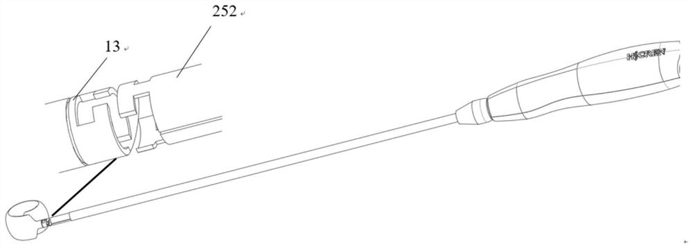
[0039] see Figure 4 , the above fusion device body 1 includes a balloon 12 and a stent 121 covered by the above balloon 12, the balloon 12 can be folded to meet the requirements of minimally invasive implantation of the fusion device; the stent 121 is pre-shaped into an approximately ellipse The shape is covered in the balloon 12; the distal head 11 and the proximal head 13 are fixed inside the closure of the two ends of the above-mentioned balloon 12, and the above-mentioned fixing method is to attach a layer of film to the closure of the two ends of the balloon 12, The balloon 12 is fixed to the small bosses of the distal head 11 and the proximal head 13 respectively;

[0040] see Figure 1-3 and 5-6, the above-menti...


PUM


Abstract

The invention discloses an intervertebral fusion system under a spine total endoscope. The intervertebral fusion system comprises an intervertebral fusion cage, a handle instrument, a bone cement injection assembly and a bone cement injection assembly. The intervertebral fusion cage is coiled into a preset shape under the action of a guide wire at the far end of the bone cement injection assembly, bone cement is poured into the fusion cage through the bone cement injection assembly, the bone cement stably supports intervertebral spaces after being solidified, the bone cement is poured through the bone cement injection assembly, remaining intervertebral space cavities are filled with the bone cement, and the postoperative fusion effect is achieved. According to the intervertebral fusion system under the spine total endoscope, whole-course visual surgical operation in a spine endoscope channel can be achieved, the operation is safer, minimally invasive spine endoscope operation is achieved, the operation is more minimally invasive, nerve traction and harassment are reduced, the risk of postoperative nerve complications is reduced, bleeding in the operation is reduced, the prognosis effect of a patient is improved, and the operation time is shortened.

Description

technical field [0001] The invention relates to the field of medical instruments, in particular to a spine total endoscopic intervertebral fusion system. Background technique [0002] Degenerative diseases of the spine and its structural damage are an important cause of neck, shoulder, waist, and leg pain, sensory and motor function impairment or even loss. In the 1950s, Cloward first proposed Posterior Lumbar Fusion (PLIF), which has developed into one of the basic procedures of spinal surgery today. In 1986, Badgy and Kuslich designed an intervertebral fusion device (Cage) suitable for the human body, namely the BAK system. Since then, intervertebral bone graft fusion technology has been greatly developed and has become a basic surgical method for the treatment of spinal degenerative diseases and structural injuries. [0003] The principle of the intervertebral fusion device is centered on the diseased intervertebral space. After the intervertebral fusion device is impla...

Claims


Application Information

Patent Timeline
Patent Type & Authority Applications(China)
IPC IPC(8): A61F2/44A61F2/46
CPCA61F2/4455A61F2/4601A61F2/4611
Inventor 姚益奇姚柏艇卓清山张鹏云
Owner NINGBO HICREN BIOTECH
Learn More